
User Manual


Table Of Contents
- VUE Key Layout
- VUE Soft keys
- Single Axis VUE Tool, and Datum keys
- Readout Parameter Access Code
- Access to Machine Parameter Operations
- Introduction
- Software Version
- VUE
- Symbols within Notes
- VUE Fonts
- Warranty
- Warranty Information:
- I – 1 Fundamentals of Positioning
- Datums
- Actual Position, Nominal Position, and Distance-To-Go
- Absolute Workpiece Positions
- Incremental workpiece positions
- Zero Angle Reference Axis
- Reading head position
- Encoder Reference Marks
- I – 2 General Operations for VUE
- Screen Layout
- VUE Hard Keys
- Power Up
- Reference Mark Evaluation
- Working without reference mark evaluation
- ENABLE/DISABLE REF function
- Operating Modes
- Setup
- Job Setup Parameters
- Units
- Scale Factor
- Mirror
- Diameter Axes
- Near Zero Warning
- Status Bar Settings
- Job Clock
- Console Adjustment
- Language
- Import/Export
- Set/Zero Soft Key
- I – 3 Milling Specific Operations
- Key Functions Detailed
- Tool Hard Key
- Tool Table
- Import/Export
- Tool Radius Compensation feature
- Sign for the length difference DL
- Calling the Tool from the Tool Table
- Datum Setting
- Datum Setting with a Tool
- Presets
- Absolute Distance Preset
- Preparation:
- Incremental Distance Preset
- 1/2 Hard Key
- Circle, and Linear Pattern
- Functions for milling pattern soft keys
- Circle pattern
- Linear Pattern
- Incline & Arc Milling
- Incline Milling
- Arc Milling
- I – 4 Turning Specific Operations
- Key Functions Detailed
- Tool Table
- Tool Display Icon
- Setting Tool Offsets with Tool/Set
- Import/Export
- Setting Tool Offsets with Lock Axis Function
- Calling a Tool from the Tool Table
- Datum Setting
- Setting Datums using LOCK AXIS Function
- Taper Calculator Hard Key
- Presets
- Radius/Diameter Soft Key
- Vectoring
- Coupling
- Z Coupling (turning applications only)
- Enabling Z Coupling
- Disabling Z Coupling
- II – 1 Installation Setup
- Installation Setup Parameters
- Exporting the current Installation Setup:
- Importing a new Tool Table
- Encoder Setup
- Display Configuration
- Error Compensation
- Linear Error Compensation
- Non-Linear Error Compensation
- Starting a Non-linear Error Compensation Table
- Configuring the Compensation Table
- Reading the Graph
- Viewing the Compensation Table
- Exporting the Current Compensation Table
- Importing a New Compensation Table
- Backlash Compensation
- Counter Settings
- Diagnostics
- Keypad Test
- Display Test
- II – 2 Installation and Electrical Connections
- Installation
- Electrical requirements
- Environmental
- Preventative maintenance
- II – 3 Dimensions
- Overview
- Accessory ID Number
10 I
I – 2 General Operations for VUE
Operating Modes
The VUE has two operating modes: Distance-To-Go (incremental),
and Actual Value (absolute). The Distance-To-Go feature enables an
approach to nominal positions by traversing to display value zero.
When working within the incremental mode, enter nominal
coordinates as either incremental, or absolute dimensions. The Actual
Value feature always displays the current actual position of the tool,
relative to the active datum. In this mode, all moves are made by
traveling until the display matches the nominal position that is
required.
While in the absolute (Actual Value) mode, if the VUE is configured for
Milling applications, only the tool length offsets are active. Both the
diameter, and length offsets are used in the incremental (Distance-To-
Go) mode to calculate the amount of “distance-to-go” required to get
to the desired nominal position relative to the edge of the tool that will
be doing the cutting.
If the VUE is configured for turning, all tool offsets are used in both the
absolute, and incremental modes.
8 Press the ABS/INC hard key to toggle between these two modes.
To view other soft key functions in either absolute, or incremental
mode, use the LEFT/RIGHT arrow keys.
Setup
VUE offers two categories for setting up operating parameters. These
categories are: Installation Setup and Job Setup. The Job Setup
parameters are used to accommodate specific machining
requirements for each job. Installation Setup is used to establish
encoder, display and communication parameters.
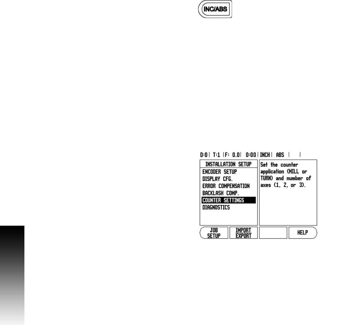
The Installation Setup menu is accessed by pressing the SETUP soft
key, then the INSTALLATION SETUP soft key. When in the Installation
Setup menu, the following soft keys will be available:
JOB SETUP: Press to begin accessing the Job Setup parameters.
IMPORT/EXPORT: Press to begin importing or exporting operating
parameters. See "Import/Export" on page 13.
HELP: Will open on-line help.
8 To view, and change Installation Setup parameters, first press the
SETUP soft key, then the INSTALLATION SETUP soft key.
8 Use the UP/DOWN arrow keys to highlight the parameters
of interest.
8 press the ENTER key.