
User Manual


Table Of Contents
- VUE Key Layout
- VUE Soft keys
- Single Axis VUE Tool, and Datum keys
- Readout Parameter Access Code
- Access to Machine Parameter Operations
- Introduction
- Software Version
- VUE
- Symbols within Notes
- VUE Fonts
- Warranty
- Warranty Information:
- I – 1 Fundamentals of Positioning
- Datums
- Actual Position, Nominal Position, and Distance-To-Go
- Absolute Workpiece Positions
- Incremental workpiece positions
- Zero Angle Reference Axis
- Reading head position
- Encoder Reference Marks
- I – 2 General Operations for VUE
- Screen Layout
- VUE Hard Keys
- Power Up
- Reference Mark Evaluation
- Working without reference mark evaluation
- ENABLE/DISABLE REF function
- Operating Modes
- Setup
- Job Setup Parameters
- Units
- Scale Factor
- Mirror
- Diameter Axes
- Near Zero Warning
- Status Bar Settings
- Job Clock
- Console Adjustment
- Language
- Import/Export
- Set/Zero Soft Key
- I – 3 Milling Specific Operations
- Key Functions Detailed
- Tool Hard Key
- Tool Table
- Import/Export
- Tool Radius Compensation feature
- Sign for the length difference DL
- Calling the Tool from the Tool Table
- Datum Setting
- Datum Setting with a Tool
- Presets
- Absolute Distance Preset
- Preparation:
- Incremental Distance Preset
- 1/2 Hard Key
- Circle, and Linear Pattern
- Functions for milling pattern soft keys
- Circle pattern
- Linear Pattern
- Incline & Arc Milling
- Incline Milling
- Arc Milling
- I – 4 Turning Specific Operations
- Key Functions Detailed
- Tool Table
- Tool Display Icon
- Setting Tool Offsets with Tool/Set
- Import/Export
- Setting Tool Offsets with Lock Axis Function
- Calling a Tool from the Tool Table
- Datum Setting
- Setting Datums using LOCK AXIS Function
- Taper Calculator Hard Key
- Presets
- Radius/Diameter Soft Key
- Vectoring
- Coupling
- Z Coupling (turning applications only)
- Enabling Z Coupling
- Disabling Z Coupling
- II – 1 Installation Setup
- Installation Setup Parameters
- Exporting the current Installation Setup:
- Importing a new Tool Table
- Encoder Setup
- Display Configuration
- Error Compensation
- Linear Error Compensation
- Non-Linear Error Compensation
- Starting a Non-linear Error Compensation Table
- Configuring the Compensation Table
- Reading the Graph
- Viewing the Compensation Table
- Exporting the Current Compensation Table
- Importing a New Compensation Table
- Backlash Compensation
- Counter Settings
- Diagnostics
- Keypad Test
- Display Test
- II – 2 Installation and Electrical Connections
- Installation
- Electrical requirements
- Environmental
- Preventative maintenance
- II – 3 Dimensions
- Overview
- Accessory ID Number
6 I
I – 2 General Operations for VUE
I – 2 General Operations for VUE
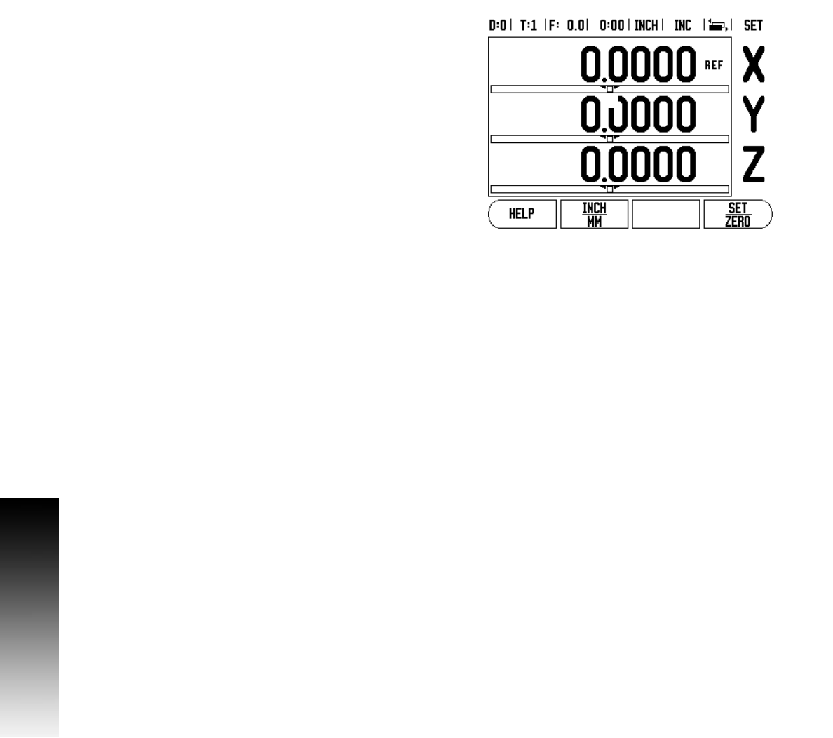
Screen Layout
Status Bar Symbols:
The VUE readout provides application-specific features that allows the
most productivity from a manual machine tool.
Status Bar - This displays the current datum tool, feed rate, job
clock time, unit of measure, operating mode status, page indicator,
and set/zero. See Job Setup for details on setting up the Status Bar
parameters.
Display Area - Indicates the current position of each axis. Also
shows forms fields instruction boxes, error messages, and help
topics.
Axis Labels - Indicates axis for corresponding axis key.
Ref Symbols - Indicates current reference mark status.
Soft key Labels - Indicates the various milling, or turning functions.
1 Datum
2 Tool
3 Feed Rate
4 Job Clock
5 Unit of Measure
6 Operating Modes
7 Page Indicator
8 Set/Zero
9 Axis Labels
10 Reference Symbol
11 Soft key Labels
12 Display Area
13 Near Zero Warning (In Distance-To-Go mode only)
9
10
4
5
1
6
7
8
2
1
11
12
13
3