
Manual


Table Of Contents
- Controls of the 3500i
- Manual Information
- Introduction
- Machining Fundamentals
- Manual Data Input
- Tool Management
- 4.1 Tool Table
- 4.2 Tool Data
- Program Management
- Conversational Editing
- Programming: Canned Cycles, sub-programs
- 7.1 Explaining Basic Cycles
- Round/Chamfer
- Rapid
- Line
- Arc
- Dwell:
- Plane Selection
- Reference Point Return:
- Fixture Offset (Work Coordinate System Select):
- Unit (Inch/MM)
- Dimension (Abs/Inc)
- Absolute Zero Set
- Block Form
- Temporary Path Tolerance
- System Data
- FeedRate
- FeedRate (4th-Axis)
- Spindle RPM
- M - Functions
- Tool Definition and Activation
- Repeat Blocks
- 7.2 Canned Cycles
- 7.3 Probing Cycles
- 7.4 Sub-programs
- 7.1 Explaining Basic Cycles
- Drawing Programs
- Running a Program on the Machine
- CAM: Programming
- 10.1 CAM Programming
- CAM Mode
- Recommended CAM Programming Sequence
- CAM Mode Mouse Operations
- CAM Mode Screen
- Activating CAM Mode
- Creating a New Program
- Tool Path Data Input
- Quick Coordinate Entry
- Job Setup: Basic tab
- Job Setup: Advanced tab
- Comment Tab
- Block Form: Basic tab
- Comment Tab
- Drilling Cycle:
- Drilling dialogue:
- Mill Cycle
- Pocket Cycle
- Pocket Finish Cycles
- Engraving Cycle
- Program Directive
- Modifying Toolbar
- Viewing Tools
- CAM Mode buttons
- CAM Setup
- Geometry
- DXF Import Feature
- Modifying Tools
- Shapes
- Tool Table
- Tool Paths
- CAM Example 1
- CAM Example 2
- 10.1 CAM Programming
- G-Code Edit, Help, & Advanced Features
- 11.1 G-Code Program Editing
- 11.2 G-Code and M-Code Definitions
- 11.3 Edit Help
- 11.4 Advanced Programming
- SPEED
- M - Functions
- Order of Execution
- Programming Non-modal Exact Stop:
- In-Position Mode (Exact Stop Check):
- Contouring Mode (Cutting Mode) :
- Setting Stroke Limit:
- Return from Reference Point:
- Move Reference from Machine Datum:
- Modifiers
- Block Separators
- Tool Offset Modification
- Expressions and Functions
- System Variables
- User Variables
- Variable Programming (Parametric Programming)
- Probe Move (G31)
- Conditional Statements
- Short Form Addressing
- Logical and Comparative Terms
- File Inclusion
- 11.5 Four Axis Programming
- Software Update
- Off-Line Software
62 4 Tool Management
4.1 Tool Table
Editing the tool table
With the tool table open, it can now be edited by changing existing
information, or adding a new tools information.
Find the required tool by using the arrow keys, and/or scroll bars.
Touch the desired field to make changes.
Type in a new value, and touch the Enter button, or touch another
field.
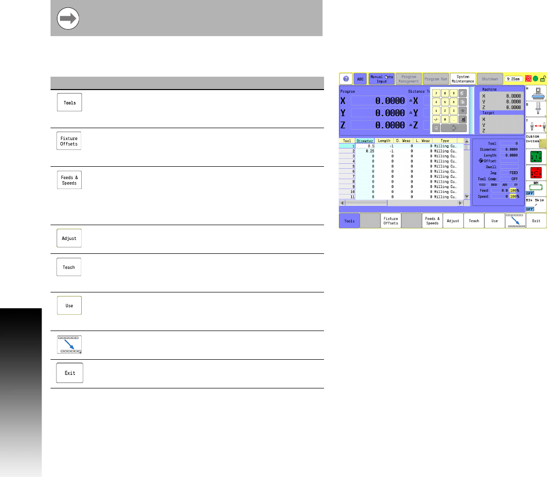
Tool Table Menu Bar
The following is a description the lower menu bar buttons available.
The bottom bar menus are described on the following
pages.
Button Function
Tools button when activated displays the tool table
showing all tools that have been programmed into
the 3500i.
Fixture Offsets opens the offset table for data
entry. Up to 100 fixture offsets can be stored on the
table.
Feeds & Speeds opens the table where data can be
entered for each tool in the tool table when in Tool
mode. Certain fields will be calculated by the 3500i
based on the data input (e.g. Number of Teeth +
Surface Speed, and Spindle Speed in calculated).
Adjust opens the dialogue to adjust the current data
of a tool in any column that is highlighted.
Teach uses the current machine position for the
selected tool.
Use opens the dialogue Use Feature which asks if
you would like the current selected tool (or Fixture
Offset if in Fixture Offset mode) to be activated.
Touch the next menu button to activate the next
button bar.
Exit closes the Tool Table.