
Manual


Table Of Contents
- Controls of the 3500i
- Manual Information
- Introduction
- Machining Fundamentals
- Manual Data Input
- Tool Management
- 4.1 Tool Table
- 4.2 Tool Data
- Program Management
- Conversational Editing
- Programming: Canned Cycles, sub-programs
- 7.1 Explaining Basic Cycles
- Round/Chamfer
- Rapid
- Line
- Arc
- Dwell:
- Plane Selection
- Reference Point Return:
- Fixture Offset (Work Coordinate System Select):
- Unit (Inch/MM)
- Dimension (Abs/Inc)
- Absolute Zero Set
- Block Form
- Temporary Path Tolerance
- System Data
- FeedRate
- FeedRate (4th-Axis)
- Spindle RPM
- M - Functions
- Tool Definition and Activation
- Repeat Blocks
- 7.2 Canned Cycles
- 7.3 Probing Cycles
- 7.4 Sub-programs
- 7.1 Explaining Basic Cycles
- Drawing Programs
- Running a Program on the Machine
- CAM: Programming
- 10.1 CAM Programming
- CAM Mode
- Recommended CAM Programming Sequence
- CAM Mode Mouse Operations
- CAM Mode Screen
- Activating CAM Mode
- Creating a New Program
- Tool Path Data Input
- Quick Coordinate Entry
- Job Setup: Basic tab
- Job Setup: Advanced tab
- Comment Tab
- Block Form: Basic tab
- Comment Tab
- Drilling Cycle:
- Drilling dialogue:
- Mill Cycle
- Pocket Cycle
- Pocket Finish Cycles
- Engraving Cycle
- Program Directive
- Modifying Toolbar
- Viewing Tools
- CAM Mode buttons
- CAM Setup
- Geometry
- DXF Import Feature
- Modifying Tools
- Shapes
- Tool Table
- Tool Paths
- CAM Example 1
- CAM Example 2
- 10.1 CAM Programming
- G-Code Edit, Help, & Advanced Features
- 11.1 G-Code Program Editing
- 11.2 G-Code and M-Code Definitions
- 11.3 Edit Help
- 11.4 Advanced Programming
- SPEED
- M - Functions
- Order of Execution
- Programming Non-modal Exact Stop:
- In-Position Mode (Exact Stop Check):
- Contouring Mode (Cutting Mode) :
- Setting Stroke Limit:
- Return from Reference Point:
- Move Reference from Machine Datum:
- Modifiers
- Block Separators
- Tool Offset Modification
- Expressions and Functions
- System Variables
- User Variables
- Variable Programming (Parametric Programming)
- Probe Move (G31)
- Conditional Statements
- Short Form Addressing
- Logical and Comparative Terms
- File Inclusion
- 11.5 Four Axis Programming
- Software Update
- Off-Line Software
ACU-RITE 3500i 55
3.1 Manual Data Input (MDI)
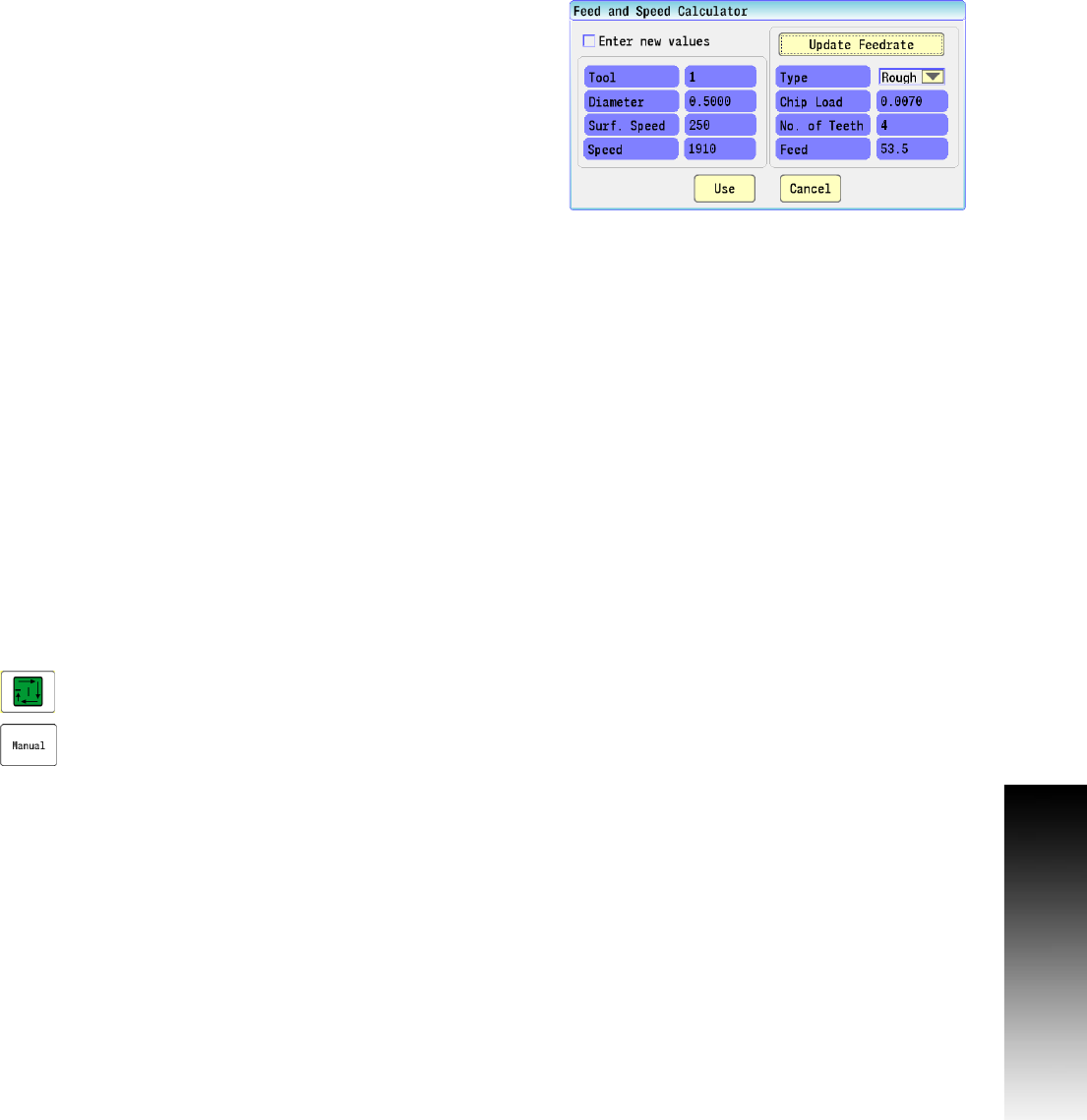
Feed and Speed
This allows the operator to adjust the current feed and speed. There
are two modes for this, each having it’s own dialogue. When the
current active tool has values entered for the feed and speeds in the
tool table the “Feed and Speed Calculator” dialogue will open.
This dialogue allows the operator to use the feed and speed values as
is from the Feed and Speed tool table. The operator can also manually
enter new values or adjust the feed depending on a new speed value
entered.
Touch the Feed and Speed Location zone.
This example describes the Feed and Speed Calculator dialogue
showing the current active tool having values entered for the feed
and speed in the tool table.
First, select the type of operation that is to executed in the Type field
drop down menu.
To adjust the values directly, check the Enter New Values check box
and enter new values for Speed or Feed by touching the activated
edit fields and entering new values.
To adjust the Feed by entering a new Speed value, check the Enter
New Values check box.
Touch the activated Speed edit field, and enter the new speed value.
Touch the Update Feedrate button.
The new feedrate will be calculated using this new speed value as
will as the other parameters shown (e.g. tool diamenter, chip load,
and number of teeth).
Touch Use to activate the changes, or press Cancel to exit without
changing the active feed and speed.
When the Use button is touched, the operator will be prompted to
“Press Start to run operation or Manual to cancel”.
Press the Start button to execute the change, or:
Touch the Manual button to cancel all changes.
See "Feeds & Speeds Overview" on page 68.