
Manual


Table Of Contents
- Controls of the 3500i
- Manual Information
- Introduction
- Machining Fundamentals
- Manual Data Input
- Tool Management
- 4.1 Tool Table
- 4.2 Tool Data
- Program Management
- Conversational Editing
- Programming: Canned Cycles, sub-programs
- 7.1 Explaining Basic Cycles
- Round/Chamfer
- Rapid
- Line
- Arc
- Dwell:
- Plane Selection
- Reference Point Return:
- Fixture Offset (Work Coordinate System Select):
- Unit (Inch/MM)
- Dimension (Abs/Inc)
- Absolute Zero Set
- Block Form
- Temporary Path Tolerance
- System Data
- FeedRate
- FeedRate (4th-Axis)
- Spindle RPM
- M - Functions
- Tool Definition and Activation
- Repeat Blocks
- 7.2 Canned Cycles
- 7.3 Probing Cycles
- 7.4 Sub-programs
- 7.1 Explaining Basic Cycles
- Drawing Programs
- Running a Program on the Machine
- CAM: Programming
- 10.1 CAM Programming
- CAM Mode
- Recommended CAM Programming Sequence
- CAM Mode Mouse Operations
- CAM Mode Screen
- Activating CAM Mode
- Creating a New Program
- Tool Path Data Input
- Quick Coordinate Entry
- Job Setup: Basic tab
- Job Setup: Advanced tab
- Comment Tab
- Block Form: Basic tab
- Comment Tab
- Drilling Cycle:
- Drilling dialogue:
- Mill Cycle
- Pocket Cycle
- Pocket Finish Cycles
- Engraving Cycle
- Program Directive
- Modifying Toolbar
- Viewing Tools
- CAM Mode buttons
- CAM Setup
- Geometry
- DXF Import Feature
- Modifying Tools
- Shapes
- Tool Table
- Tool Paths
- CAM Example 1
- CAM Example 2
- 10.1 CAM Programming
- G-Code Edit, Help, & Advanced Features
- 11.1 G-Code Program Editing
- 11.2 G-Code and M-Code Definitions
- 11.3 Edit Help
- 11.4 Advanced Programming
- SPEED
- M - Functions
- Order of Execution
- Programming Non-modal Exact Stop:
- In-Position Mode (Exact Stop Check):
- Contouring Mode (Cutting Mode) :
- Setting Stroke Limit:
- Return from Reference Point:
- Move Reference from Machine Datum:
- Modifiers
- Block Separators
- Tool Offset Modification
- Expressions and Functions
- System Variables
- User Variables
- Variable Programming (Parametric Programming)
- Probe Move (G31)
- Conditional Statements
- Short Form Addressing
- Logical and Comparative Terms
- File Inclusion
- 11.5 Four Axis Programming
- Software Update
- Off-Line Software
42 3 Manual Data Input
3.1 Manual Data Input (MDI)
Manual Data Input Operations
The following explains a few of the machining operations that are
available with Manual Data Input. Examples have been provided to
explain an overview to the operator of the 3500i’s capabilities.
The Drill Cycles, Pocket Cycles, and Other Cycles buttons access
sub menus of different types of cycles that are available in each of
these categories.
A cycle, or operation is ran by pressing Use. While running a graphic
representation can be seen by touching the Draw button. The Manual
button can be touched at anytime to cancel an operation.
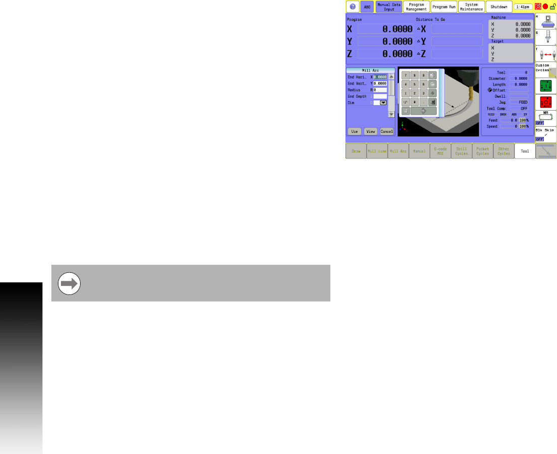
Mill Arc manual data input
From the bottom menu bar touch the Mill Arc button.
The touch screen displays a graphic of an arc milling operation, and
the highlight bar is positioned in the first field on the form that is
requiring data input.
The numeric pad is also displayed to enter data into the field. The
Use button can be touched once all fields have been entered, or the
data input can be canceled at any time by touching the Cancel
button.
When the data has been entered, touch the Enter button on the
numeric pad.
The highlight bar will go to the next required field input, and the
graphic view changes to display graphically the next required data
input.
When the data has been entered, touch the Enter button again on
the numeric pad.
The above steps repeat for each data entry, and the display continues
to change, showing what is required for the data entry.
In addition to the required parameters, the More button can be
touched to show additional data entry inputs when this button is
available. The More button is not available on all menus.
The buttons Use, View, and Cancel are common to all
Manual Data Input forms.