
Manual


Table Of Contents
- Controls of the 3500i
- Manual Information
- Introduction
- Machining Fundamentals
- Manual Data Input
- Tool Management
- 4.1 Tool Table
- 4.2 Tool Data
- Program Management
- Conversational Editing
- Programming: Canned Cycles, sub-programs
- 7.1 Explaining Basic Cycles
- Round/Chamfer
- Rapid
- Line
- Arc
- Dwell:
- Plane Selection
- Reference Point Return:
- Fixture Offset (Work Coordinate System Select):
- Unit (Inch/MM)
- Dimension (Abs/Inc)
- Absolute Zero Set
- Block Form
- Temporary Path Tolerance
- System Data
- FeedRate
- FeedRate (4th-Axis)
- Spindle RPM
- M - Functions
- Tool Definition and Activation
- Repeat Blocks
- 7.2 Canned Cycles
- 7.3 Probing Cycles
- 7.4 Sub-programs
- 7.1 Explaining Basic Cycles
- Drawing Programs
- Running a Program on the Machine
- CAM: Programming
- 10.1 CAM Programming
- CAM Mode
- Recommended CAM Programming Sequence
- CAM Mode Mouse Operations
- CAM Mode Screen
- Activating CAM Mode
- Creating a New Program
- Tool Path Data Input
- Quick Coordinate Entry
- Job Setup: Basic tab
- Job Setup: Advanced tab
- Comment Tab
- Block Form: Basic tab
- Comment Tab
- Drilling Cycle:
- Drilling dialogue:
- Mill Cycle
- Pocket Cycle
- Pocket Finish Cycles
- Engraving Cycle
- Program Directive
- Modifying Toolbar
- Viewing Tools
- CAM Mode buttons
- CAM Setup
- Geometry
- DXF Import Feature
- Modifying Tools
- Shapes
- Tool Table
- Tool Paths
- CAM Example 1
- CAM Example 2
- 10.1 CAM Programming
- G-Code Edit, Help, & Advanced Features
- 11.1 G-Code Program Editing
- 11.2 G-Code and M-Code Definitions
- 11.3 Edit Help
- 11.4 Advanced Programming
- SPEED
- M - Functions
- Order of Execution
- Programming Non-modal Exact Stop:
- In-Position Mode (Exact Stop Check):
- Contouring Mode (Cutting Mode) :
- Setting Stroke Limit:
- Return from Reference Point:
- Move Reference from Machine Datum:
- Modifiers
- Block Separators
- Tool Offset Modification
- Expressions and Functions
- System Variables
- User Variables
- Variable Programming (Parametric Programming)
- Probe Move (G31)
- Conditional Statements
- Short Form Addressing
- Logical and Comparative Terms
- File Inclusion
- 11.5 Four Axis Programming
- Software Update
- Off-Line Software
40 3 Manual Data Input
3.1 Manual Data Input (MDI)
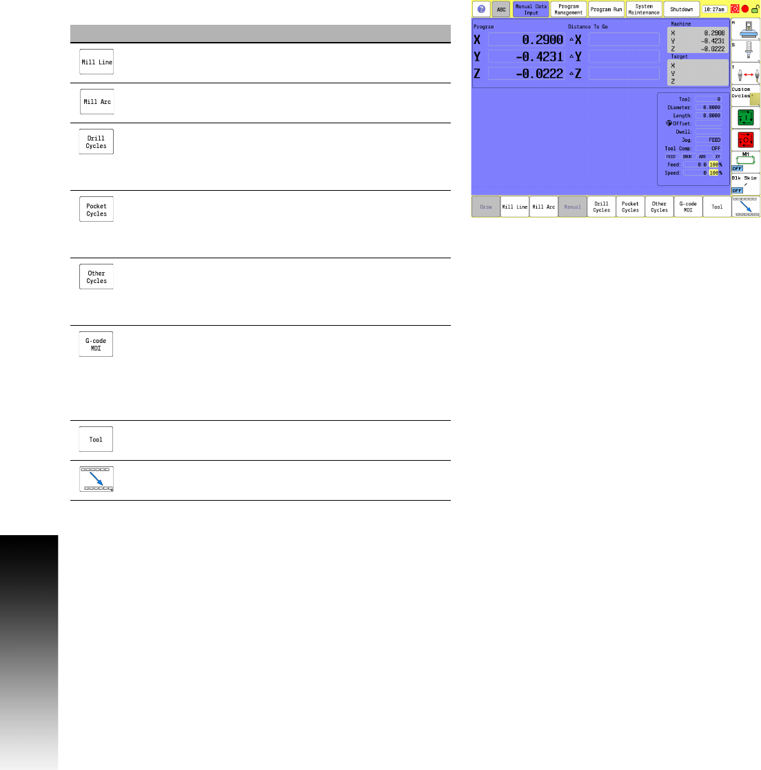
Manual Data Input Menu Bar
The following table describes the bottom bar menu buttons.
Button Function
Mill Line opens the Mill Line pop-up dialogue
where information can be entered to mill a line.
Mill Arc opens the Mill Arc pop-up dialogue where
information can be entered to mill an arc (or radius).
Drill Cycles opens a sub menu for selection of type
of drilling cycle, e.g. Basic, Pecking, Counter Bore
etc.). Selection of a cycle opens a form for data
input.
Pocket Cycles opens a sub menu for selection of
type of pocket cycle, e.g. Circular, Rectangular, Slot,
etc.). Selection of a cycle opens a form for data
input.
Other Cycles opens a sub menu for selection of type
of other cycles, e.g. Face, Tool Probing, Linear
Engraving, etc.). Section of a cycle opens a form for
data input.
G-code MDI toggles the 3500i between standard
Manual Data Input, and G-code Manual Data Input
mode. The G-code MDI opens up a text editor for the
operator to allow single G-code commands to be
entered. Blocks are inserted for multiple machining
operations using the G-code, or ISO format.
Tool opens the Tool Table.
Touch the next menu button to activate the next
button bar.