
Manual


Table Of Contents
- Controls of the 3500i
- Manual Information
- Introduction
- Machining Fundamentals
- Manual Data Input
- Tool Management
- 4.1 Tool Table
- 4.2 Tool Data
- Program Management
- Conversational Editing
- Programming: Canned Cycles, sub-programs
- 7.1 Explaining Basic Cycles
- Round/Chamfer
- Rapid
- Line
- Arc
- Dwell:
- Plane Selection
- Reference Point Return:
- Fixture Offset (Work Coordinate System Select):
- Unit (Inch/MM)
- Dimension (Abs/Inc)
- Absolute Zero Set
- Block Form
- Temporary Path Tolerance
- System Data
- FeedRate
- FeedRate (4th-Axis)
- Spindle RPM
- M - Functions
- Tool Definition and Activation
- Repeat Blocks
- 7.2 Canned Cycles
- 7.3 Probing Cycles
- 7.4 Sub-programs
- 7.1 Explaining Basic Cycles
- Drawing Programs
- Running a Program on the Machine
- CAM: Programming
- 10.1 CAM Programming
- CAM Mode
- Recommended CAM Programming Sequence
- CAM Mode Mouse Operations
- CAM Mode Screen
- Activating CAM Mode
- Creating a New Program
- Tool Path Data Input
- Quick Coordinate Entry
- Job Setup: Basic tab
- Job Setup: Advanced tab
- Comment Tab
- Block Form: Basic tab
- Comment Tab
- Drilling Cycle:
- Drilling dialogue:
- Mill Cycle
- Pocket Cycle
- Pocket Finish Cycles
- Engraving Cycle
- Program Directive
- Modifying Toolbar
- Viewing Tools
- CAM Mode buttons
- CAM Setup
- Geometry
- DXF Import Feature
- Modifying Tools
- Shapes
- Tool Table
- Tool Paths
- CAM Example 1
- CAM Example 2
- 10.1 CAM Programming
- G-Code Edit, Help, & Advanced Features
- 11.1 G-Code Program Editing
- 11.2 G-Code and M-Code Definitions
- 11.3 Edit Help
- 11.4 Advanced Programming
- SPEED
- M - Functions
- Order of Execution
- Programming Non-modal Exact Stop:
- In-Position Mode (Exact Stop Check):
- Contouring Mode (Cutting Mode) :
- Setting Stroke Limit:
- Return from Reference Point:
- Move Reference from Machine Datum:
- Modifiers
- Block Separators
- Tool Offset Modification
- Expressions and Functions
- System Variables
- User Variables
- Variable Programming (Parametric Programming)
- Probe Move (G31)
- Conditional Statements
- Short Form Addressing
- Logical and Comparative Terms
- File Inclusion
- 11.5 Four Axis Programming
- Software Update
- Off-Line Software
32 2 Machining Fundamentals
2.1 Fundamentals of Positioning
Setting the datum
Fixture Offsets
A production drawing identifies a certain form element of the work
piece, usually a corner, as the absolute zero datum. When setting the
datum, you first align the work piece along the machine axes, and then
move the tool in each axis to a defined position relative to the work
piece. Set the display of the CNC either to zero or to a known position
value for each position. This establishes the reference system for the
work piece, which will be used for the CNC display and your part
program.
If the production drawing is not dimensioned for that particular CNC,
set the datum at a position or corner on the work piece which is
suitable for deducing the dimensions of the remaining work piece
positions.
The fastest, easiest and most accurate way of setting the datum is by
using a 3-D touch probe from HEIDENHAIN Corp. Refer to chapter "7.3
Probing Cycles on page 199”.
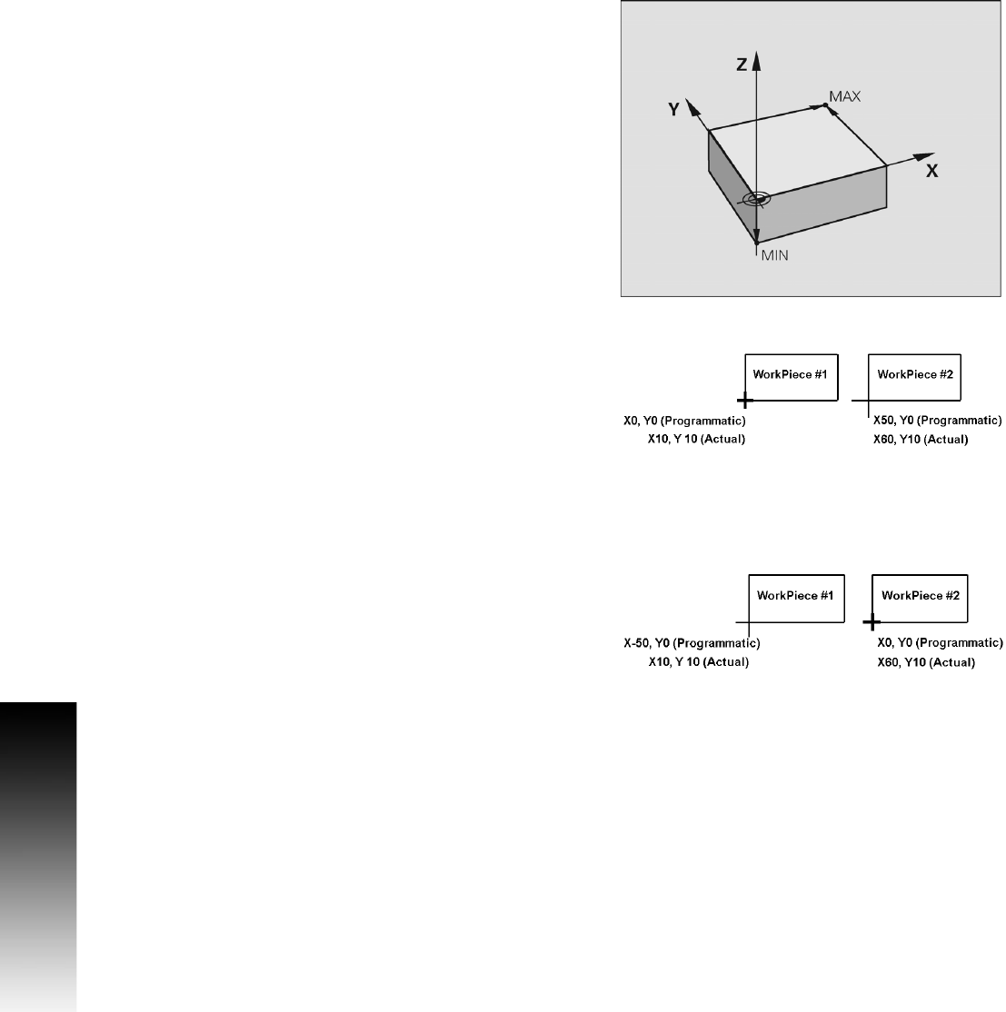
Example 1: Offset
See "Fixture Offset (Work Coordinate System Select):" on page 138 for
more information on using the Offset cycle. Use the Offset command
to apply a Fixture Offset of the absolute zero datum to the corner of
WorkPiece #1.
Format: Offset Fixture #1 X10 Y10
Offset Fixture #1
Machining positions are now referenced from the lower left corner of
WorkPiece #1.
Use the Offset command to apply a Fixture Offset of the absolute
zero datum to the corner of WorkPiece #2.
Format: Offset Fixture #2 X60 Y10
Offset Fixture #2
Machining positions are now referenced from the lower left corner of
WorkPiece #2.