
Manual


Table Of Contents
- Controls of the 3500i
- Manual Information
- Introduction
- Machining Fundamentals
- Manual Data Input
- Tool Management
- 4.1 Tool Table
- 4.2 Tool Data
- Program Management
- Conversational Editing
- Programming: Canned Cycles, sub-programs
- 7.1 Explaining Basic Cycles
- Round/Chamfer
- Rapid
- Line
- Arc
- Dwell:
- Plane Selection
- Reference Point Return:
- Fixture Offset (Work Coordinate System Select):
- Unit (Inch/MM)
- Dimension (Abs/Inc)
- Absolute Zero Set
- Block Form
- Temporary Path Tolerance
- System Data
- FeedRate
- FeedRate (4th-Axis)
- Spindle RPM
- M - Functions
- Tool Definition and Activation
- Repeat Blocks
- 7.2 Canned Cycles
- 7.3 Probing Cycles
- 7.4 Sub-programs
- 7.1 Explaining Basic Cycles
- Drawing Programs
- Running a Program on the Machine
- CAM: Programming
- 10.1 CAM Programming
- CAM Mode
- Recommended CAM Programming Sequence
- CAM Mode Mouse Operations
- CAM Mode Screen
- Activating CAM Mode
- Creating a New Program
- Tool Path Data Input
- Quick Coordinate Entry
- Job Setup: Basic tab
- Job Setup: Advanced tab
- Comment Tab
- Block Form: Basic tab
- Comment Tab
- Drilling Cycle:
- Drilling dialogue:
- Mill Cycle
- Pocket Cycle
- Pocket Finish Cycles
- Engraving Cycle
- Program Directive
- Modifying Toolbar
- Viewing Tools
- CAM Mode buttons
- CAM Setup
- Geometry
- DXF Import Feature
- Modifying Tools
- Shapes
- Tool Table
- Tool Paths
- CAM Example 1
- CAM Example 2
- 10.1 CAM Programming
- G-Code Edit, Help, & Advanced Features
- 11.1 G-Code Program Editing
- 11.2 G-Code and M-Code Definitions
- 11.3 Edit Help
- 11.4 Advanced Programming
- SPEED
- M - Functions
- Order of Execution
- Programming Non-modal Exact Stop:
- In-Position Mode (Exact Stop Check):
- Contouring Mode (Cutting Mode) :
- Setting Stroke Limit:
- Return from Reference Point:
- Move Reference from Machine Datum:
- Modifiers
- Block Separators
- Tool Offset Modification
- Expressions and Functions
- System Variables
- User Variables
- Variable Programming (Parametric Programming)
- Probe Move (G31)
- Conditional Statements
- Short Form Addressing
- Logical and Comparative Terms
- File Inclusion
- 11.5 Four Axis Programming
- Software Update
- Off-Line Software
ACU-RITE 3500i 27
2.1 Fundamentals of Positioning
Reference system
A reference system is required to define positions in a plane or in
space. The position data are always referenced to a predetermined
point and are described through coordinates.
The Cartesian coordinate system (a rectangular coordinate system) is
based on the three coordinate axes X, Y and Z. The axes are mutually
perpendicular and intersect at one point called the datum. A
coordinate identifies the distance from the datum in one of these
directions. A position in a plane is thus described through two
coordinates, and a position in space through three coordinates.
Coordinates that are referenced to the datum are referred to as
absolute coordinates. Relative coordinates are referenced to any other
known position (reference point) you define within the coordinate
system. Relative coordinate values are also referred to as incremental
coordinate values.
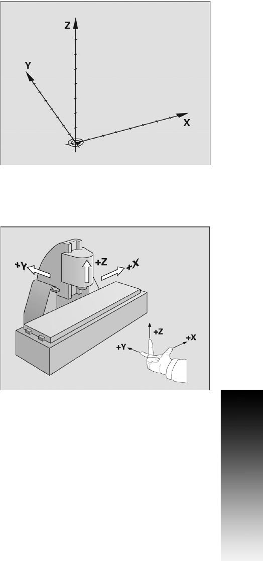
Reference system on milling machines
When using a milling machine, you orient tool movements to the
Cartesian coordinate system. The illustration at right shows how the
Cartesian coordinate system describes the machine axes. The figure
illustrates the right-hand rule for remembering the three axis
directions: the middle finger points in the positive direction of the tool
axis from the work piece toward the tool (the Z axis), the thumb points
in the positive X direction, and the index finger in the positive Y
direction.
The CNC 3500i can control 3 or 4 axes optionally. The 4th axis is
designated by the letter “U”. The “U” axis function depends on the
builder.