
Manual


Table Of Contents
- Controls of the 3500i
- Manual Information
- Introduction
- Machining Fundamentals
- Manual Data Input
- Tool Management
- 4.1 Tool Table
- 4.2 Tool Data
- Program Management
- Conversational Editing
- Programming: Canned Cycles, sub-programs
- 7.1 Explaining Basic Cycles
- Round/Chamfer
- Rapid
- Line
- Arc
- Dwell:
- Plane Selection
- Reference Point Return:
- Fixture Offset (Work Coordinate System Select):
- Unit (Inch/MM)
- Dimension (Abs/Inc)
- Absolute Zero Set
- Block Form
- Temporary Path Tolerance
- System Data
- FeedRate
- FeedRate (4th-Axis)
- Spindle RPM
- M - Functions
- Tool Definition and Activation
- Repeat Blocks
- 7.2 Canned Cycles
- 7.3 Probing Cycles
- 7.4 Sub-programs
- 7.1 Explaining Basic Cycles
- Drawing Programs
- Running a Program on the Machine
- CAM: Programming
- 10.1 CAM Programming
- CAM Mode
- Recommended CAM Programming Sequence
- CAM Mode Mouse Operations
- CAM Mode Screen
- Activating CAM Mode
- Creating a New Program
- Tool Path Data Input
- Quick Coordinate Entry
- Job Setup: Basic tab
- Job Setup: Advanced tab
- Comment Tab
- Block Form: Basic tab
- Comment Tab
- Drilling Cycle:
- Drilling dialogue:
- Mill Cycle
- Pocket Cycle
- Pocket Finish Cycles
- Engraving Cycle
- Program Directive
- Modifying Toolbar
- Viewing Tools
- CAM Mode buttons
- CAM Setup
- Geometry
- DXF Import Feature
- Modifying Tools
- Shapes
- Tool Table
- Tool Paths
- CAM Example 1
- CAM Example 2
- 10.1 CAM Programming
- G-Code Edit, Help, & Advanced Features
- 11.1 G-Code Program Editing
- 11.2 G-Code and M-Code Definitions
- 11.3 Edit Help
- 11.4 Advanced Programming
- SPEED
- M - Functions
- Order of Execution
- Programming Non-modal Exact Stop:
- In-Position Mode (Exact Stop Check):
- Contouring Mode (Cutting Mode) :
- Setting Stroke Limit:
- Return from Reference Point:
- Move Reference from Machine Datum:
- Modifiers
- Block Separators
- Tool Offset Modification
- Expressions and Functions
- System Variables
- User Variables
- Variable Programming (Parametric Programming)
- Probe Move (G31)
- Conditional Statements
- Short Form Addressing
- Logical and Comparative Terms
- File Inclusion
- 11.5 Four Axis Programming
- Software Update
- Off-Line Software
ACU-RITE 3500i 23
1.4 Accessories:
1.4 Accessories:
Available accessories include a selection of electronic Touch Probes,
and Hand Wheels.
Touch probes
Touch Probe Function software option.
With the various HEIDENHAIN 3-D touch probe systems you can:
Automatically align work pieces
Quickly and precisely set datum
Measure the work piece during program run
Measure and inspect tools
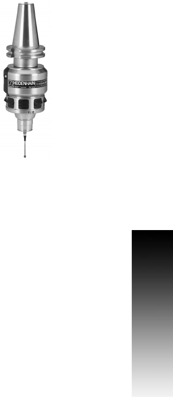
TS 220, TS 640 and TS 440 touch trigger probes
These touch probes are particularly effective for automatic work piece
alignment, datum setting and work piece measurement. The TS 220
transmits the triggering signals to the CNC via cable and is a
cost-effective alternative for applications where digitizing is not
frequently required.
The TS 640 (see figure) and the smaller TS 440 feature infrared
transmission of the triggering signal to the CNC. This makes them
highly convenient for use on machines with automatic tool changers.
Principle of operation: HEIDENHAIN triggering touch probes feature a
wear resisting optical switch that generates an electrical signal as
soon as the stylus is deflected. This signal is transmitted to the
control, which stores the current position of the stylus as an actual
value.