
Manual


Table Of Contents
- Controls of the 3500i
- Manual Information
- Introduction
- Machining Fundamentals
- Manual Data Input
- Tool Management
- 4.1 Tool Table
- 4.2 Tool Data
- Program Management
- Conversational Editing
- Programming: Canned Cycles, sub-programs
- 7.1 Explaining Basic Cycles
- Round/Chamfer
- Rapid
- Line
- Arc
- Dwell:
- Plane Selection
- Reference Point Return:
- Fixture Offset (Work Coordinate System Select):
- Unit (Inch/MM)
- Dimension (Abs/Inc)
- Absolute Zero Set
- Block Form
- Temporary Path Tolerance
- System Data
- FeedRate
- FeedRate (4th-Axis)
- Spindle RPM
- M - Functions
- Tool Definition and Activation
- Repeat Blocks
- 7.2 Canned Cycles
- 7.3 Probing Cycles
- 7.4 Sub-programs
- 7.1 Explaining Basic Cycles
- Drawing Programs
- Running a Program on the Machine
- CAM: Programming
- 10.1 CAM Programming
- CAM Mode
- Recommended CAM Programming Sequence
- CAM Mode Mouse Operations
- CAM Mode Screen
- Activating CAM Mode
- Creating a New Program
- Tool Path Data Input
- Quick Coordinate Entry
- Job Setup: Basic tab
- Job Setup: Advanced tab
- Comment Tab
- Block Form: Basic tab
- Comment Tab
- Drilling Cycle:
- Drilling dialogue:
- Mill Cycle
- Pocket Cycle
- Pocket Finish Cycles
- Engraving Cycle
- Program Directive
- Modifying Toolbar
- Viewing Tools
- CAM Mode buttons
- CAM Setup
- Geometry
- DXF Import Feature
- Modifying Tools
- Shapes
- Tool Table
- Tool Paths
- CAM Example 1
- CAM Example 2
- 10.1 CAM Programming
- G-Code Edit, Help, & Advanced Features
- 11.1 G-Code Program Editing
- 11.2 G-Code and M-Code Definitions
- 11.3 Edit Help
- 11.4 Advanced Programming
- SPEED
- M - Functions
- Order of Execution
- Programming Non-modal Exact Stop:
- In-Position Mode (Exact Stop Check):
- Contouring Mode (Cutting Mode) :
- Setting Stroke Limit:
- Return from Reference Point:
- Move Reference from Machine Datum:
- Modifiers
- Block Separators
- Tool Offset Modification
- Expressions and Functions
- System Variables
- User Variables
- Variable Programming (Parametric Programming)
- Probe Move (G31)
- Conditional Statements
- Short Form Addressing
- Logical and Comparative Terms
- File Inclusion
- 11.5 Four Axis Programming
- Software Update
- Off-Line Software
332 10 CAM: Programming
10.1 CAM Programming
CAM Example 1
Creating basic geometry for tool path usage. In this exercise a pocket
slot will be created, and completing the slot will require the use of a
tool path for clean up. The slot will be .500” wide, by 1.000” long on
center, and .375” deep. A .375” diameter end mill will be used.
Exercise One:
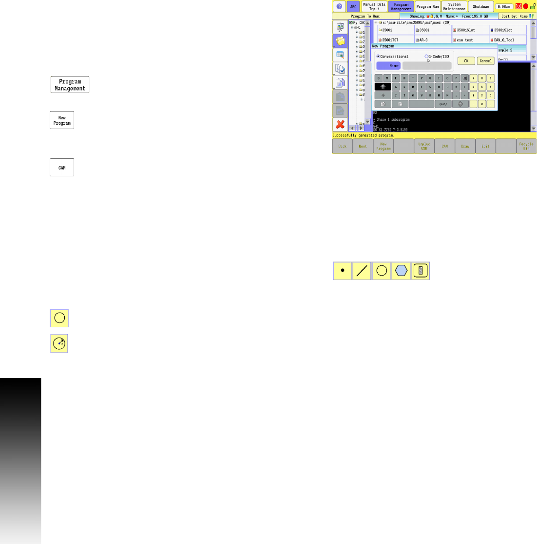
The first steps are to set up a new program for this exercise.
In Manual Data Input Mode, select the PROGRAM
MANAGEMENT button to activate the Program Directory
button.
Touch the New Program button to create a new
program, and type in the new name of the program.
Touch the G-Code/ISO box as the new program type, and then touch
Ok.
Select the CAM button.
With the new program set up, and named, the steps in this program
can now be created. The first step is to create the geometry.
Defining Geometry:
Geometry items are the basic element of CAM programming. Shapes
are created from geometry, and tool paths are generated from these
shapes.
To define geometry, the applicable button from the Geometry Tools
in the main Toolbar will need to be selected. See "Geometry Toolbar
buttons:" on page 282.
In this exercise the Circle button will be used first.
Select the Circle button from the Geometry Tools in
the main Toolbar.
Select the Create Circle button for the method to be
used to define the geometry from the vertical
Toolbar.