
Manual


Table Of Contents
- Controls of the 3500i
- Manual Information
- Introduction
- Machining Fundamentals
- Manual Data Input
- Tool Management
- 4.1 Tool Table
- 4.2 Tool Data
- Program Management
- Conversational Editing
- Programming: Canned Cycles, sub-programs
- 7.1 Explaining Basic Cycles
- Round/Chamfer
- Rapid
- Line
- Arc
- Dwell:
- Plane Selection
- Reference Point Return:
- Fixture Offset (Work Coordinate System Select):
- Unit (Inch/MM)
- Dimension (Abs/Inc)
- Absolute Zero Set
- Block Form
- Temporary Path Tolerance
- System Data
- FeedRate
- FeedRate (4th-Axis)
- Spindle RPM
- M - Functions
- Tool Definition and Activation
- Repeat Blocks
- 7.2 Canned Cycles
- 7.3 Probing Cycles
- 7.4 Sub-programs
- 7.1 Explaining Basic Cycles
- Drawing Programs
- Running a Program on the Machine
- CAM: Programming
- 10.1 CAM Programming
- CAM Mode
- Recommended CAM Programming Sequence
- CAM Mode Mouse Operations
- CAM Mode Screen
- Activating CAM Mode
- Creating a New Program
- Tool Path Data Input
- Quick Coordinate Entry
- Job Setup: Basic tab
- Job Setup: Advanced tab
- Comment Tab
- Block Form: Basic tab
- Comment Tab
- Drilling Cycle:
- Drilling dialogue:
- Mill Cycle
- Pocket Cycle
- Pocket Finish Cycles
- Engraving Cycle
- Program Directive
- Modifying Toolbar
- Viewing Tools
- CAM Mode buttons
- CAM Setup
- Geometry
- DXF Import Feature
- Modifying Tools
- Shapes
- Tool Table
- Tool Paths
- CAM Example 1
- CAM Example 2
- 10.1 CAM Programming
- G-Code Edit, Help, & Advanced Features
- 11.1 G-Code Program Editing
- 11.2 G-Code and M-Code Definitions
- 11.3 Edit Help
- 11.4 Advanced Programming
- SPEED
- M - Functions
- Order of Execution
- Programming Non-modal Exact Stop:
- In-Position Mode (Exact Stop Check):
- Contouring Mode (Cutting Mode) :
- Setting Stroke Limit:
- Return from Reference Point:
- Move Reference from Machine Datum:
- Modifiers
- Block Separators
- Tool Offset Modification
- Expressions and Functions
- System Variables
- User Variables
- Variable Programming (Parametric Programming)
- Probe Move (G31)
- Conditional Statements
- Short Form Addressing
- Logical and Comparative Terms
- File Inclusion
- 11.5 Four Axis Programming
- Software Update
- Off-Line Software
330 10 CAM: Programming
10.1 CAM Programming
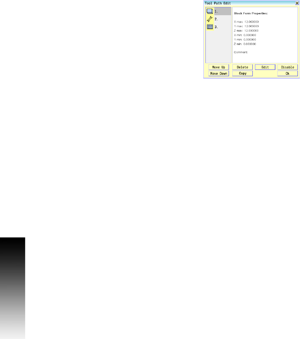
Editing a Tool Path
To edit a Tool Path:
Select the Tool Path Edit button to open the Tool Path Edit
dialogue.
Select the tool path to edit from the numbered list of tool path
buttons.
Select the Edit button. A Data dialogue opens, displaying the data
for the selected tool path.
Update the data that require editing.
Select the Use button in the data dialogue to save the changes, and
exit. A prompt appears asking to "Save the modified tool path
commands".
Disabling, and Enabling Tool Paths
To disable a Tool Path:
Open the Tool Path Edit dialogue.
Select the tool path to disable from the numbered list of tool path
buttons.
Select the Disable button. Disabled tool paths have an “X” to the
right of them in the Tool Path Edit dialogue. Blocks will not show in
program.
To enable a disabled tool path, follow these steps but select the
Enable button for a disabled tool path.
Deleting Tool Paths
To delete a Tool Path:
Open the Tool Path Edit dialogue.
Select the tool path to delete from the numbered list of tool path
buttons.
Select the Delete button. A delete confirmation dialogue will
pop-up.
Select the Yes button to confirm tool path deletion, or No to cancel.
Arranging Tool Paths Sequence
To arrange the Tool Path sequence:
Open the Tool Path Edit dialogue.
Select a tool path from the numbered list of tool path buttons
Select the Move Up, or Move Down button. This will move the selected
tool path, and change the order in which it is executed in the
program.