
Manual


Table Of Contents
- Controls of the 3500i
- Manual Information
- Introduction
- Machining Fundamentals
- Manual Data Input
- Tool Management
- 4.1 Tool Table
- 4.2 Tool Data
- Program Management
- Conversational Editing
- Programming: Canned Cycles, sub-programs
- 7.1 Explaining Basic Cycles
- Round/Chamfer
- Rapid
- Line
- Arc
- Dwell:
- Plane Selection
- Reference Point Return:
- Fixture Offset (Work Coordinate System Select):
- Unit (Inch/MM)
- Dimension (Abs/Inc)
- Absolute Zero Set
- Block Form
- Temporary Path Tolerance
- System Data
- FeedRate
- FeedRate (4th-Axis)
- Spindle RPM
- M - Functions
- Tool Definition and Activation
- Repeat Blocks
- 7.2 Canned Cycles
- 7.3 Probing Cycles
- 7.4 Sub-programs
- 7.1 Explaining Basic Cycles
- Drawing Programs
- Running a Program on the Machine
- CAM: Programming
- 10.1 CAM Programming
- CAM Mode
- Recommended CAM Programming Sequence
- CAM Mode Mouse Operations
- CAM Mode Screen
- Activating CAM Mode
- Creating a New Program
- Tool Path Data Input
- Quick Coordinate Entry
- Job Setup: Basic tab
- Job Setup: Advanced tab
- Comment Tab
- Block Form: Basic tab
- Comment Tab
- Drilling Cycle:
- Drilling dialogue:
- Mill Cycle
- Pocket Cycle
- Pocket Finish Cycles
- Engraving Cycle
- Program Directive
- Modifying Toolbar
- Viewing Tools
- CAM Mode buttons
- CAM Setup
- Geometry
- DXF Import Feature
- Modifying Tools
- Shapes
- Tool Table
- Tool Paths
- CAM Example 1
- CAM Example 2
- 10.1 CAM Programming
- G-Code Edit, Help, & Advanced Features
- 11.1 G-Code Program Editing
- 11.2 G-Code and M-Code Definitions
- 11.3 Edit Help
- 11.4 Advanced Programming
- SPEED
- M - Functions
- Order of Execution
- Programming Non-modal Exact Stop:
- In-Position Mode (Exact Stop Check):
- Contouring Mode (Cutting Mode) :
- Setting Stroke Limit:
- Return from Reference Point:
- Move Reference from Machine Datum:
- Modifiers
- Block Separators
- Tool Offset Modification
- Expressions and Functions
- System Variables
- User Variables
- Variable Programming (Parametric Programming)
- Probe Move (G31)
- Conditional Statements
- Short Form Addressing
- Logical and Comparative Terms
- File Inclusion
- 11.5 Four Axis Programming
- Software Update
- Off-Line Software
ACU-RITE 3500i 329
10.1 CAM Programming
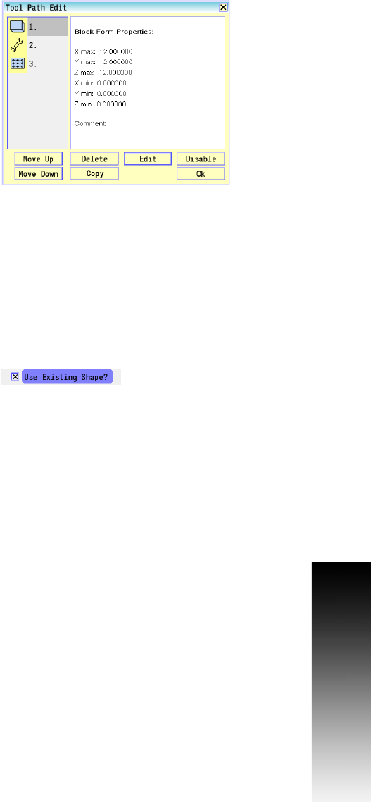
Tool Path Editing
The tool path edit dialogue allows editing, and arranging existing tool
paths in the program. Tool path operations are used to generate the
CNC program. The program is generated in the order in which the tool
paths are created. The Tool Path Edit feature can be used to change
the order of tool path operations, or edit a specific tool path. Select
the Tool Path Edit button to display the Tool Path Edit dialogue.
Tool Path buttons:
Move Up: Moves the selected Tool Path up in the programming
order.
Move Down: Moves the selected Tool Path down in the
programming order.
Delete: Deletes the selected Tool Path.
Copy: Copies the selected tool path and places a copy of that tool
path at the end of the programming order. The copied Tool path can
be re-ordered by using Move Up and Move Down buttons.
Edit: Activates the selected Tool Path's parameters dialogue. Use
the parameters dialogue to edit any parameters for the Tool Path.
Disable: Disables the selected Tool Path. A disabled tool path will
not be used when the program is generated and is marked with an
“X” in the tool path list.
OK: Closes the Tool Path Edit dialogue.
Use Existing Shape
When editing tool paths that require shapes, an existing shape
associated with the tool path can be used, or select an entirely
different shape. To use the existing shape touch inside the Use
Existing Shape checkbox. To use a new shape leave this box
unchecked. After touching the Use button you will be prompted to
select a new shape for the tool path.