
Manual


Table Of Contents
- Controls of the 3500i
- Manual Information
- Introduction
- Machining Fundamentals
- Manual Data Input
- Tool Management
- 4.1 Tool Table
- 4.2 Tool Data
- Program Management
- Conversational Editing
- Programming: Canned Cycles, sub-programs
- 7.1 Explaining Basic Cycles
- Round/Chamfer
- Rapid
- Line
- Arc
- Dwell:
- Plane Selection
- Reference Point Return:
- Fixture Offset (Work Coordinate System Select):
- Unit (Inch/MM)
- Dimension (Abs/Inc)
- Absolute Zero Set
- Block Form
- Temporary Path Tolerance
- System Data
- FeedRate
- FeedRate (4th-Axis)
- Spindle RPM
- M - Functions
- Tool Definition and Activation
- Repeat Blocks
- 7.2 Canned Cycles
- 7.3 Probing Cycles
- 7.4 Sub-programs
- 7.1 Explaining Basic Cycles
- Drawing Programs
- Running a Program on the Machine
- CAM: Programming
- 10.1 CAM Programming
- CAM Mode
- Recommended CAM Programming Sequence
- CAM Mode Mouse Operations
- CAM Mode Screen
- Activating CAM Mode
- Creating a New Program
- Tool Path Data Input
- Quick Coordinate Entry
- Job Setup: Basic tab
- Job Setup: Advanced tab
- Comment Tab
- Block Form: Basic tab
- Comment Tab
- Drilling Cycle:
- Drilling dialogue:
- Mill Cycle
- Pocket Cycle
- Pocket Finish Cycles
- Engraving Cycle
- Program Directive
- Modifying Toolbar
- Viewing Tools
- CAM Mode buttons
- CAM Setup
- Geometry
- DXF Import Feature
- Modifying Tools
- Shapes
- Tool Table
- Tool Paths
- CAM Example 1
- CAM Example 2
- 10.1 CAM Programming
- G-Code Edit, Help, & Advanced Features
- 11.1 G-Code Program Editing
- 11.2 G-Code and M-Code Definitions
- 11.3 Edit Help
- 11.4 Advanced Programming
- SPEED
- M - Functions
- Order of Execution
- Programming Non-modal Exact Stop:
- In-Position Mode (Exact Stop Check):
- Contouring Mode (Cutting Mode) :
- Setting Stroke Limit:
- Return from Reference Point:
- Move Reference from Machine Datum:
- Modifiers
- Block Separators
- Tool Offset Modification
- Expressions and Functions
- System Variables
- User Variables
- Variable Programming (Parametric Programming)
- Probe Move (G31)
- Conditional Statements
- Short Form Addressing
- Logical and Comparative Terms
- File Inclusion
- 11.5 Four Axis Programming
- Software Update
- Off-Line Software
8 1 Introduction
1.2 Visual Display Unit
General Operating Guidelines
The following provides the general operating guidelines for the 3500i.
Mode specific function buttons are always located on the left
vertical edge of the screen.
Scroll bars automatically appear when the window information does
not completely fit into the current window size.
The active operating mode is highlighted in blue in the top menu bar.
The activated key in the side bar will highlight in blue also. More
than one key may be activated at a time depending on the action
being taken. Available selection keys for the current activity are
highlighted. Non-available keys are grayed out.
Use the Context Sensitive Help feature when assistance is desired.
This is an intuitive feature that aids the user by going directly to the
section in the manual in relation to the feature, or button that you
select to obtain assistance with.
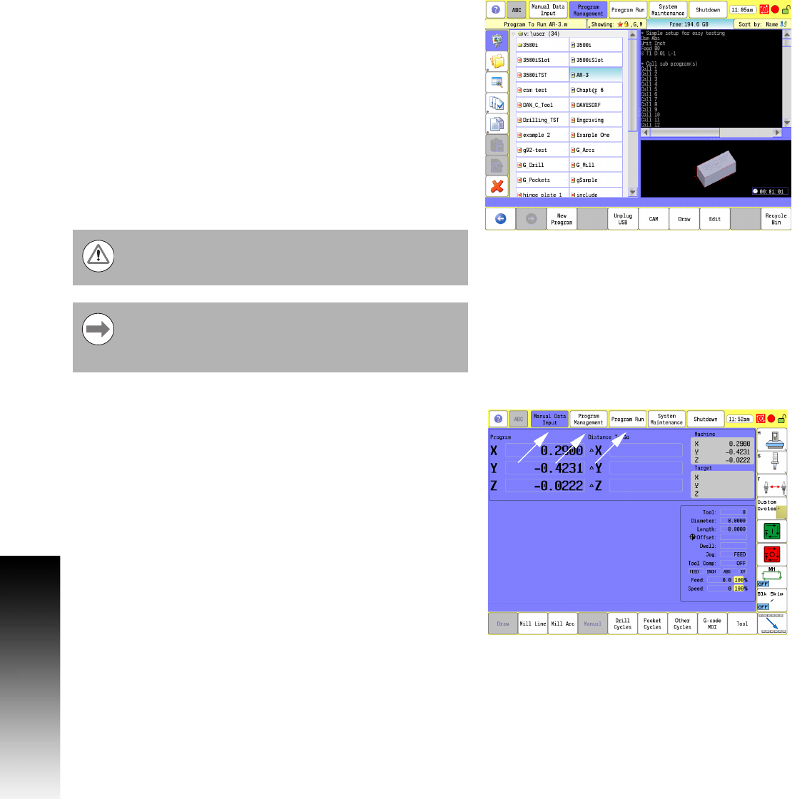
Main Operating Modes
The ACU-RITE 3500i has three main operating modes: Manual Data
Input (MDI), Program Management, and Program Run. These are
accessed with the large rectangular buttons at the top of the screen.
Manual Data Input allows data input for simple machining
operations. Manual operation, single step operation, and single
commands can be entered. See "Manual Data Input Menu Bar" on
page 40 for a complete description.
It is important to understand that this manual is written
with the assumption that the user is using the touch
screen.
A USB pointing device e.g. mouse, trackball, etc. may also
be used. If a device is being used, the action of clicking on
a screen key corresponds to the same action as if the user
is touching the screen. A USB keyboard can also be used.