
Manual


Table Of Contents
- Controls of the 3500i
- Manual Information
- Introduction
- Machining Fundamentals
- Manual Data Input
- Tool Management
- 4.1 Tool Table
- 4.2 Tool Data
- Program Management
- Conversational Editing
- Programming: Canned Cycles, sub-programs
- 7.1 Explaining Basic Cycles
- Round/Chamfer
- Rapid
- Line
- Arc
- Dwell:
- Plane Selection
- Reference Point Return:
- Fixture Offset (Work Coordinate System Select):
- Unit (Inch/MM)
- Dimension (Abs/Inc)
- Absolute Zero Set
- Block Form
- Temporary Path Tolerance
- System Data
- FeedRate
- FeedRate (4th-Axis)
- Spindle RPM
- M - Functions
- Tool Definition and Activation
- Repeat Blocks
- 7.2 Canned Cycles
- 7.3 Probing Cycles
- 7.4 Sub-programs
- 7.1 Explaining Basic Cycles
- Drawing Programs
- Running a Program on the Machine
- CAM: Programming
- 10.1 CAM Programming
- CAM Mode
- Recommended CAM Programming Sequence
- CAM Mode Mouse Operations
- CAM Mode Screen
- Activating CAM Mode
- Creating a New Program
- Tool Path Data Input
- Quick Coordinate Entry
- Job Setup: Basic tab
- Job Setup: Advanced tab
- Comment Tab
- Block Form: Basic tab
- Comment Tab
- Drilling Cycle:
- Drilling dialogue:
- Mill Cycle
- Pocket Cycle
- Pocket Finish Cycles
- Engraving Cycle
- Program Directive
- Modifying Toolbar
- Viewing Tools
- CAM Mode buttons
- CAM Setup
- Geometry
- DXF Import Feature
- Modifying Tools
- Shapes
- Tool Table
- Tool Paths
- CAM Example 1
- CAM Example 2
- 10.1 CAM Programming
- G-Code Edit, Help, & Advanced Features
- 11.1 G-Code Program Editing
- 11.2 G-Code and M-Code Definitions
- 11.3 Edit Help
- 11.4 Advanced Programming
- SPEED
- M - Functions
- Order of Execution
- Programming Non-modal Exact Stop:
- In-Position Mode (Exact Stop Check):
- Contouring Mode (Cutting Mode) :
- Setting Stroke Limit:
- Return from Reference Point:
- Move Reference from Machine Datum:
- Modifiers
- Block Separators
- Tool Offset Modification
- Expressions and Functions
- System Variables
- User Variables
- Variable Programming (Parametric Programming)
- Probe Move (G31)
- Conditional Statements
- Short Form Addressing
- Logical and Comparative Terms
- File Inclusion
- 11.5 Four Axis Programming
- Software Update
- Off-Line Software
ACU-RITE 3500i 313
10.1 CAM Programming
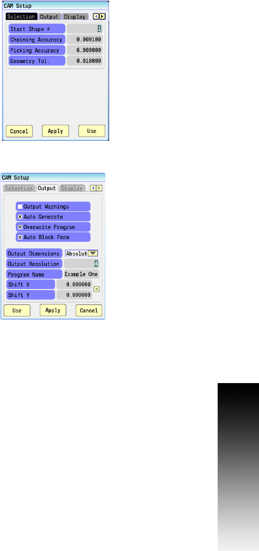
CAM Setup
The Setup button, opens the CAM Setup dialogue. There are four tabs
in this dialogue used for setting up the CAM program. Preferences,
required values, and parameters are input here.
Selection tab:
Start Shape: Default value is 1. The starting shape number during
shape selection.
Chaining Accuracy: Accuracy parameter for chaining geometry
objects during shape selection. Default value is 0.000100.
Picking Accuracy: Accuracy parameter for selecting geometry
objects with mouse. Default value is 6.000000 pixels.
Geometry Tolerance: Accuracy parameter for geometry tolerance
for internal geometry creation algorithms. Default value is 0.010000.
Output tab:
Output Dimensions: Determines to output position values as either
absolute or incremental. Default value is Absolute.
Output Warnings: Output warnings as comments when generating
program. Default value is No.
Output Resolution: Output resolution in positions after decimal
point when generating program. Default value is 4.
Program Name: Program name to use when generating program.
Default value is the name of the program currently active.
Auto Generate: Automatically generate program when CAM exits.
Default value is Yes.
Overwrite Program: Automatically overwrite the program when
saving file and not prompt to overwrite. Default value is Yes.
Shift X: Shifts all shape and tool path X values by the entered
amount in the CNC program.
Shift Y: Shifts all shape and tool path Y values by the entered
amount in the CNC program.
Auto Block Form: If checked it will automatically calculate an
estimated block form toolpath when creating a program, but only if
a block form toolpath is not manually programmed. Default is on.