
Manual


Table Of Contents
- Controls of the 3500i
- Manual Information
- Introduction
- Machining Fundamentals
- Manual Data Input
- Tool Management
- 4.1 Tool Table
- 4.2 Tool Data
- Program Management
- Conversational Editing
- Programming: Canned Cycles, sub-programs
- 7.1 Explaining Basic Cycles
- Round/Chamfer
- Rapid
- Line
- Arc
- Dwell:
- Plane Selection
- Reference Point Return:
- Fixture Offset (Work Coordinate System Select):
- Unit (Inch/MM)
- Dimension (Abs/Inc)
- Absolute Zero Set
- Block Form
- Temporary Path Tolerance
- System Data
- FeedRate
- FeedRate (4th-Axis)
- Spindle RPM
- M - Functions
- Tool Definition and Activation
- Repeat Blocks
- 7.2 Canned Cycles
- 7.3 Probing Cycles
- 7.4 Sub-programs
- 7.1 Explaining Basic Cycles
- Drawing Programs
- Running a Program on the Machine
- CAM: Programming
- 10.1 CAM Programming
- CAM Mode
- Recommended CAM Programming Sequence
- CAM Mode Mouse Operations
- CAM Mode Screen
- Activating CAM Mode
- Creating a New Program
- Tool Path Data Input
- Quick Coordinate Entry
- Job Setup: Basic tab
- Job Setup: Advanced tab
- Comment Tab
- Block Form: Basic tab
- Comment Tab
- Drilling Cycle:
- Drilling dialogue:
- Mill Cycle
- Pocket Cycle
- Pocket Finish Cycles
- Engraving Cycle
- Program Directive
- Modifying Toolbar
- Viewing Tools
- CAM Mode buttons
- CAM Setup
- Geometry
- DXF Import Feature
- Modifying Tools
- Shapes
- Tool Table
- Tool Paths
- CAM Example 1
- CAM Example 2
- 10.1 CAM Programming
- G-Code Edit, Help, & Advanced Features
- 11.1 G-Code Program Editing
- 11.2 G-Code and M-Code Definitions
- 11.3 Edit Help
- 11.4 Advanced Programming
- SPEED
- M - Functions
- Order of Execution
- Programming Non-modal Exact Stop:
- In-Position Mode (Exact Stop Check):
- Contouring Mode (Cutting Mode) :
- Setting Stroke Limit:
- Return from Reference Point:
- Move Reference from Machine Datum:
- Modifiers
- Block Separators
- Tool Offset Modification
- Expressions and Functions
- System Variables
- User Variables
- Variable Programming (Parametric Programming)
- Probe Move (G31)
- Conditional Statements
- Short Form Addressing
- Logical and Comparative Terms
- File Inclusion
- 11.5 Four Axis Programming
- Software Update
- Off-Line Software
ACU-RITE 3500i 307
10.1 CAM Programming
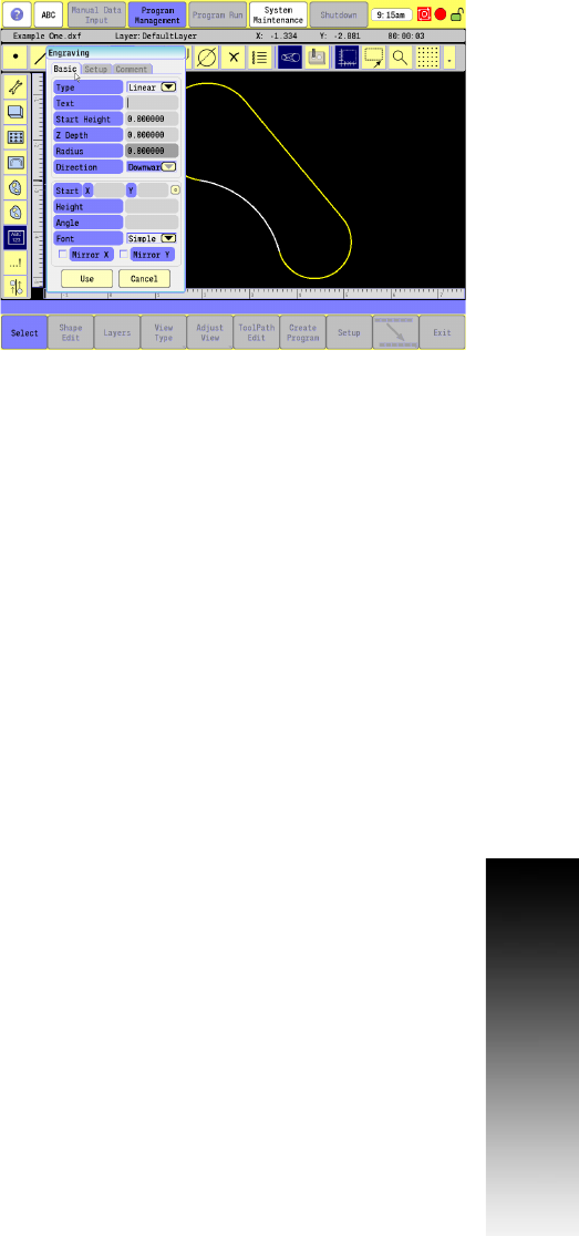
Engraving Cycle
The Engraving Cycle provides a quick and easy way to engrave part
numbers, legends, or any alpha/numeric inscription. Engraving does
not require the use of shapes or geometry. There are two types of
engraving patterns, Linear and Circular. Certain parameters apply only
to specific cycles. These parameters appear as needed. The usual
type of cutter is a sharp point or center-drill type tool. Options are
given for engraving on an angle and mirror is supported for engraving
molds. When executed, the CNC rapids to the X Start, Y Start, then to
the Start Height. It then feeds to the Z Depth and begins cutting the
Text specified.
Basic tab:
Type: Choose Linear or Circular engraving.
Text: Enter the text to be engraved. Upper and lower case
characters, numbers and punctuation are allowed.
Start Height: Enter the Absolute Z position before beginning the
engrave cycle.
Z Depth: Enter the Z absolute depth of engraving.
Radius (Circular): Enter the radius for circular engraving.
Direction (Circular): Choose a direction, Downward or Upward, for
circular engraving.
Start X: Enter the X coordinate for lower-left corner of the text.
Start Y: Enter the Y coordinate for lower-left corner of the text.
Height: Enter the letter height.
Angle: Enter the angle in degrees for rotating the text to be
engraved.
Font: Choose Simple, Stencil or Stick.
Mirror X: Select to mirror the engraving on the X axis.
Mirror Y: Select to mirror the engraving on the Y axis.