
Manual


Table Of Contents
- Controls of the 3500i
- Manual Information
- Introduction
- Machining Fundamentals
- Manual Data Input
- Tool Management
- 4.1 Tool Table
- 4.2 Tool Data
- Program Management
- Conversational Editing
- Programming: Canned Cycles, sub-programs
- 7.1 Explaining Basic Cycles
- Round/Chamfer
- Rapid
- Line
- Arc
- Dwell:
- Plane Selection
- Reference Point Return:
- Fixture Offset (Work Coordinate System Select):
- Unit (Inch/MM)
- Dimension (Abs/Inc)
- Absolute Zero Set
- Block Form
- Temporary Path Tolerance
- System Data
- FeedRate
- FeedRate (4th-Axis)
- Spindle RPM
- M - Functions
- Tool Definition and Activation
- Repeat Blocks
- 7.2 Canned Cycles
- 7.3 Probing Cycles
- 7.4 Sub-programs
- 7.1 Explaining Basic Cycles
- Drawing Programs
- Running a Program on the Machine
- CAM: Programming
- 10.1 CAM Programming
- CAM Mode
- Recommended CAM Programming Sequence
- CAM Mode Mouse Operations
- CAM Mode Screen
- Activating CAM Mode
- Creating a New Program
- Tool Path Data Input
- Quick Coordinate Entry
- Job Setup: Basic tab
- Job Setup: Advanced tab
- Comment Tab
- Block Form: Basic tab
- Comment Tab
- Drilling Cycle:
- Drilling dialogue:
- Mill Cycle
- Pocket Cycle
- Pocket Finish Cycles
- Engraving Cycle
- Program Directive
- Modifying Toolbar
- Viewing Tools
- CAM Mode buttons
- CAM Setup
- Geometry
- DXF Import Feature
- Modifying Tools
- Shapes
- Tool Table
- Tool Paths
- CAM Example 1
- CAM Example 2
- 10.1 CAM Programming
- G-Code Edit, Help, & Advanced Features
- 11.1 G-Code Program Editing
- 11.2 G-Code and M-Code Definitions
- 11.3 Edit Help
- 11.4 Advanced Programming
- SPEED
- M - Functions
- Order of Execution
- Programming Non-modal Exact Stop:
- In-Position Mode (Exact Stop Check):
- Contouring Mode (Cutting Mode) :
- Setting Stroke Limit:
- Return from Reference Point:
- Move Reference from Machine Datum:
- Modifiers
- Block Separators
- Tool Offset Modification
- Expressions and Functions
- System Variables
- User Variables
- Variable Programming (Parametric Programming)
- Probe Move (G31)
- Conditional Statements
- Short Form Addressing
- Logical and Comparative Terms
- File Inclusion
- 11.5 Four Axis Programming
- Software Update
- Off-Line Software
ACU-RITE 3500i 303
10.1 CAM Programming
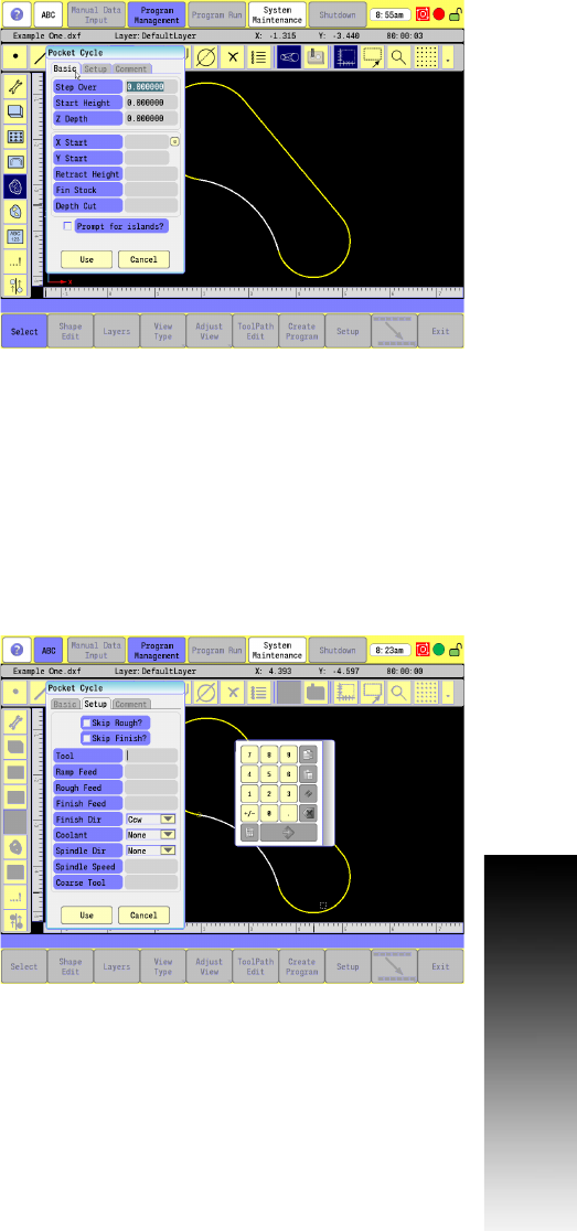
Pocket Cycle
The Pocket Cycle tool path is used to generate a pocket cycle with or
without islands from defined shapes. Islands within islands are
allowed. The cycle rapids to the X Start, Y Start point, rapids to the
Start Height and then feeds to the first Depth Cut using Ramp Feed.
The selected shape and islands are milled using Rough Feed. This
cycle continues until Z Depth is reached. Finish Feed and Finish Stock
are used for the final pass if specified. The cycle then rapid retracts to
Retract Height.
Basic tab:
Step Over: Enter the distance the tool steps over (width of cut) as
it mills out the pocket.
Start Height: Enter the Absolute Z position before beginning to mill
the pocket.
Z Depth: Enter the absolute depth of the finished pocket.
X Start: Enter the X position to start the pocket.
Y Start: Enter the Y position to start the pocket.
Retract Height: Enter the Absolute Z position at the start and end of
the cycle.
Finish Stock: Enter the Finish Stock amount.
Depth Cut: Enter the depth per pass.
Prompt for islands: Select if the pocket has islands. After shape has
been selected for the pocket you will be prompted to select shapes
for islands.
Setup tab:
Ramp Feed: Enter the ramp feed. Automatically calculated if tool
being used is defined in the Tool Table.
Ramp Feed = (Rough Feed + Finish Feed) ÷ 2.
Rough Feed: Enter the XY axes roughing feed rate.
Finish Feed: Enter the XY axes finish feed rate.
Tool: Enter the tool number to use for the cycle.
Coolant: Choose None, On (M8), Off (M9), or Mist (M7). See
"Coolant" on page 292.
Spindle Dir: Choose Forward, Reverse, Off or None. See "Spindle
Direction" on page 292.