
Manual


Table Of Contents
- Controls of the 3500i
- Manual Information
- Introduction
- Machining Fundamentals
- Manual Data Input
- Tool Management
- 4.1 Tool Table
- 4.2 Tool Data
- Program Management
- Conversational Editing
- Programming: Canned Cycles, sub-programs
- 7.1 Explaining Basic Cycles
- Round/Chamfer
- Rapid
- Line
- Arc
- Dwell:
- Plane Selection
- Reference Point Return:
- Fixture Offset (Work Coordinate System Select):
- Unit (Inch/MM)
- Dimension (Abs/Inc)
- Absolute Zero Set
- Block Form
- Temporary Path Tolerance
- System Data
- FeedRate
- FeedRate (4th-Axis)
- Spindle RPM
- M - Functions
- Tool Definition and Activation
- Repeat Blocks
- 7.2 Canned Cycles
- 7.3 Probing Cycles
- 7.4 Sub-programs
- 7.1 Explaining Basic Cycles
- Drawing Programs
- Running a Program on the Machine
- CAM: Programming
- 10.1 CAM Programming
- CAM Mode
- Recommended CAM Programming Sequence
- CAM Mode Mouse Operations
- CAM Mode Screen
- Activating CAM Mode
- Creating a New Program
- Tool Path Data Input
- Quick Coordinate Entry
- Job Setup: Basic tab
- Job Setup: Advanced tab
- Comment Tab
- Block Form: Basic tab
- Comment Tab
- Drilling Cycle:
- Drilling dialogue:
- Mill Cycle
- Pocket Cycle
- Pocket Finish Cycles
- Engraving Cycle
- Program Directive
- Modifying Toolbar
- Viewing Tools
- CAM Mode buttons
- CAM Setup
- Geometry
- DXF Import Feature
- Modifying Tools
- Shapes
- Tool Table
- Tool Paths
- CAM Example 1
- CAM Example 2
- 10.1 CAM Programming
- G-Code Edit, Help, & Advanced Features
- 11.1 G-Code Program Editing
- 11.2 G-Code and M-Code Definitions
- 11.3 Edit Help
- 11.4 Advanced Programming
- SPEED
- M - Functions
- Order of Execution
- Programming Non-modal Exact Stop:
- In-Position Mode (Exact Stop Check):
- Contouring Mode (Cutting Mode) :
- Setting Stroke Limit:
- Return from Reference Point:
- Move Reference from Machine Datum:
- Modifiers
- Block Separators
- Tool Offset Modification
- Expressions and Functions
- System Variables
- User Variables
- Variable Programming (Parametric Programming)
- Probe Move (G31)
- Conditional Statements
- Short Form Addressing
- Logical and Comparative Terms
- File Inclusion
- 11.5 Four Axis Programming
- Software Update
- Off-Line Software
ACU-RITE 3500i 281
10.1 CAM Programming
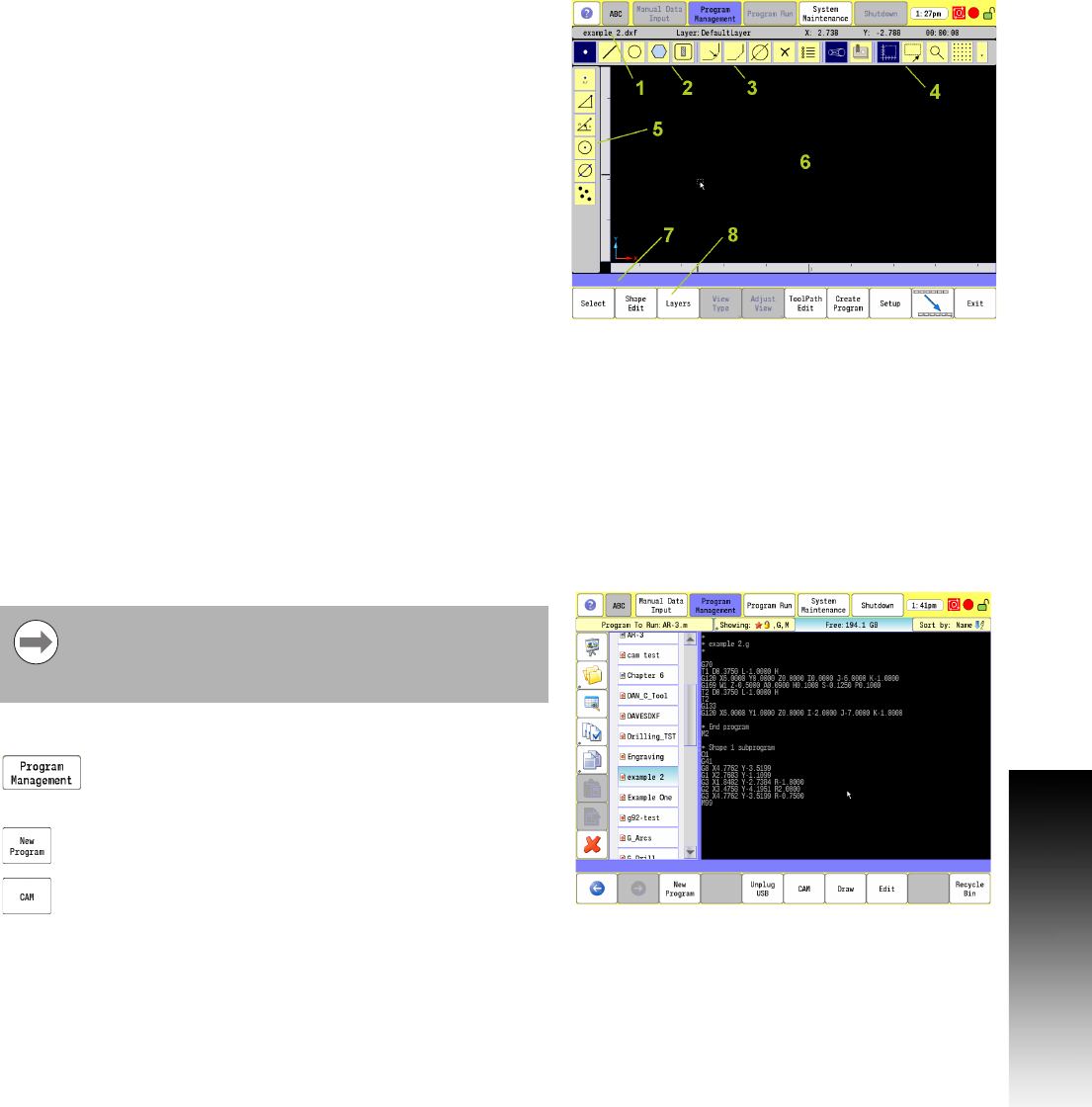
CAM Mode Screen
In CAM Mode the CNC displays the CAM Mode screen.
The CAM Mode screen Displays three groups of icons, and one
Toolbar on the left:
Geometry Toolbar menu 2.
Modifying Toolbar menu 3.
Viewing Toolbar menu 4.
Vertical button bar example 5. The Side tool bar changes depending
on the geometry tool selected.
Activating CAM Mode
To activate CAM Mode:
In Manual Data Input Mode, select the Program
Management button to activate the Program Directory
button.
Touch the New Program button to create a new
program.
Select the CAM button.
The CAM screen activates.
1
Status Bar: Displays the program name, active layer and mouse
cursor position, and estimated machining time.
2
Main Toolbar (Section 1): Geometry Tools, Modifying Tools,
Viewing Tools.
3 Main Toolbar (Section 2): Modifying Tools.
4 Main Toolbar (Section 3): Viewing Tools.
5 Side Toolbar: Displays options for Geometry Tools.
6 Graphics Display Area: Displays geometry, shape and Tool Paths.
7
Message, and Prompt Display: Displays messages or prompts
user for input.
8
Buttons: Offer various functionality based on tool type or button
chosen.
CAM must be used with a program. This can be an
existing program or a new program. Care must be taken
when using an existing program, CAM will overwrite the
program.