
Manual


Table Of Contents
- Controls of the 3500i
- Manual Information
- Introduction
- Machining Fundamentals
- Manual Data Input
- Tool Management
- 4.1 Tool Table
- 4.2 Tool Data
- Program Management
- Conversational Editing
- Programming: Canned Cycles, sub-programs
- 7.1 Explaining Basic Cycles
- Round/Chamfer
- Rapid
- Line
- Arc
- Dwell:
- Plane Selection
- Reference Point Return:
- Fixture Offset (Work Coordinate System Select):
- Unit (Inch/MM)
- Dimension (Abs/Inc)
- Absolute Zero Set
- Block Form
- Temporary Path Tolerance
- System Data
- FeedRate
- FeedRate (4th-Axis)
- Spindle RPM
- M - Functions
- Tool Definition and Activation
- Repeat Blocks
- 7.2 Canned Cycles
- 7.3 Probing Cycles
- 7.4 Sub-programs
- 7.1 Explaining Basic Cycles
- Drawing Programs
- Running a Program on the Machine
- CAM: Programming
- 10.1 CAM Programming
- CAM Mode
- Recommended CAM Programming Sequence
- CAM Mode Mouse Operations
- CAM Mode Screen
- Activating CAM Mode
- Creating a New Program
- Tool Path Data Input
- Quick Coordinate Entry
- Job Setup: Basic tab
- Job Setup: Advanced tab
- Comment Tab
- Block Form: Basic tab
- Comment Tab
- Drilling Cycle:
- Drilling dialogue:
- Mill Cycle
- Pocket Cycle
- Pocket Finish Cycles
- Engraving Cycle
- Program Directive
- Modifying Toolbar
- Viewing Tools
- CAM Mode buttons
- CAM Setup
- Geometry
- DXF Import Feature
- Modifying Tools
- Shapes
- Tool Table
- Tool Paths
- CAM Example 1
- CAM Example 2
- 10.1 CAM Programming
- G-Code Edit, Help, & Advanced Features
- 11.1 G-Code Program Editing
- 11.2 G-Code and M-Code Definitions
- 11.3 Edit Help
- 11.4 Advanced Programming
- SPEED
- M - Functions
- Order of Execution
- Programming Non-modal Exact Stop:
- In-Position Mode (Exact Stop Check):
- Contouring Mode (Cutting Mode) :
- Setting Stroke Limit:
- Return from Reference Point:
- Move Reference from Machine Datum:
- Modifiers
- Block Separators
- Tool Offset Modification
- Expressions and Functions
- System Variables
- User Variables
- Variable Programming (Parametric Programming)
- Probe Move (G31)
- Conditional Statements
- Short Form Addressing
- Logical and Comparative Terms
- File Inclusion
- 11.5 Four Axis Programming
- Software Update
- Off-Line Software
268 9 Running a Program on the Machine
9.1 Running a program
Single Step
Single-Step Mode runs a program block by block. This mode enables
you to step through the program and verify the moves before you
cut an actual part.
Once a program has been selected, and the Program Run mode has
been activated, touch the Single Step. button.
Touch the START button to execute each block or motion.
Touch the STOP button to stop, or pause the block or motion.
Touch the Manual button to cancel a program that is on hold.
When you cancel a program, the 3500i terminates tool
compensation and canned cycles. All other modal settings remain
active.
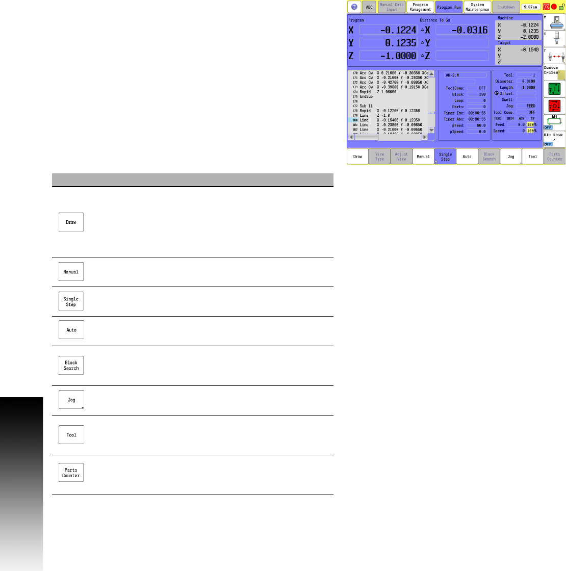
The following table list the active buttons in the Single Step, and Auto
screen.
Button Function
Draw activates the real-time graphic view window.
The View Type button activates the sub menu of
view options. The Adjust View button activates the
sub menu for view adjustment for the Draw screen.
Refer to Chapter 8, "View Options Menu" on page
258.
Manual cancels the currently active program run
session.
Single Step changes to Single-Step Mode.
Auto Changes to Auto Mode. Use to run part
programs for production.
Block Search activates the Block Search feature.
Refer to "Using Block Search to Select a Starting
Block."
Jog displays the Jog menu.
Tool activates the Tool Table, providing easy access
to the Tool Table.
Parts Counter activates the Parts Counter dialogue,
to allow adjusting or resetting the number of
completed parts.