
Manual


Table Of Contents
- Controls of the 3500i
- Manual Information
- Introduction
- Machining Fundamentals
- Manual Data Input
- Tool Management
- 4.1 Tool Table
- 4.2 Tool Data
- Program Management
- Conversational Editing
- Programming: Canned Cycles, sub-programs
- 7.1 Explaining Basic Cycles
- Round/Chamfer
- Rapid
- Line
- Arc
- Dwell:
- Plane Selection
- Reference Point Return:
- Fixture Offset (Work Coordinate System Select):
- Unit (Inch/MM)
- Dimension (Abs/Inc)
- Absolute Zero Set
- Block Form
- Temporary Path Tolerance
- System Data
- FeedRate
- FeedRate (4th-Axis)
- Spindle RPM
- M - Functions
- Tool Definition and Activation
- Repeat Blocks
- 7.2 Canned Cycles
- 7.3 Probing Cycles
- 7.4 Sub-programs
- 7.1 Explaining Basic Cycles
- Drawing Programs
- Running a Program on the Machine
- CAM: Programming
- 10.1 CAM Programming
- CAM Mode
- Recommended CAM Programming Sequence
- CAM Mode Mouse Operations
- CAM Mode Screen
- Activating CAM Mode
- Creating a New Program
- Tool Path Data Input
- Quick Coordinate Entry
- Job Setup: Basic tab
- Job Setup: Advanced tab
- Comment Tab
- Block Form: Basic tab
- Comment Tab
- Drilling Cycle:
- Drilling dialogue:
- Mill Cycle
- Pocket Cycle
- Pocket Finish Cycles
- Engraving Cycle
- Program Directive
- Modifying Toolbar
- Viewing Tools
- CAM Mode buttons
- CAM Setup
- Geometry
- DXF Import Feature
- Modifying Tools
- Shapes
- Tool Table
- Tool Paths
- CAM Example 1
- CAM Example 2
- 10.1 CAM Programming
- G-Code Edit, Help, & Advanced Features
- 11.1 G-Code Program Editing
- 11.2 G-Code and M-Code Definitions
- 11.3 Edit Help
- 11.4 Advanced Programming
- SPEED
- M - Functions
- Order of Execution
- Programming Non-modal Exact Stop:
- In-Position Mode (Exact Stop Check):
- Contouring Mode (Cutting Mode) :
- Setting Stroke Limit:
- Return from Reference Point:
- Move Reference from Machine Datum:
- Modifiers
- Block Separators
- Tool Offset Modification
- Expressions and Functions
- System Variables
- User Variables
- Variable Programming (Parametric Programming)
- Probe Move (G31)
- Conditional Statements
- Short Form Addressing
- Logical and Comparative Terms
- File Inclusion
- 11.5 Four Axis Programming
- Software Update
- Off-Line Software
264 8 Drawing Programs
8.1 Draw
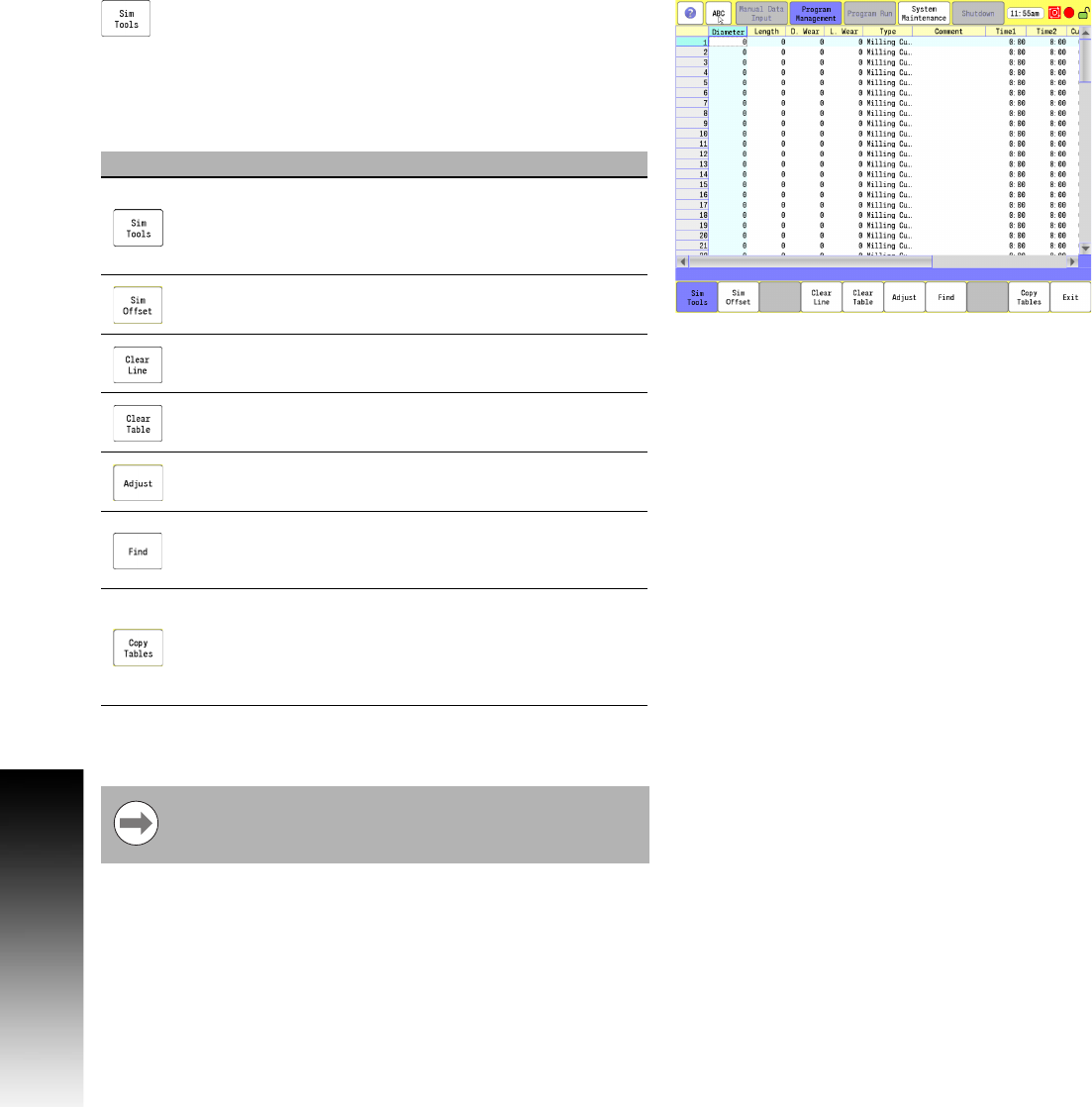
Sim Tools
Touch the Sim Tools button to activate the Draw Tool
Table.
The simulator tool table is a separate table that Draw uses to simulate
the machining of the part. The machine tool table can be copied into
the Draw tool table. Any changes made in this table does not affect
the machine tool table.
Running programs in Draw that have tool or fixture definitions only
affect the simulation tool, and fixture tables.
Button Function
Sim Tools is the table used to define the
characteristics of the tools to be used while
simulating the program. The usage behaviors are
identical to the standard machine Tool Table.
Sim Offset is the table used to define the fixture
offsets to be used when simulating the program.
Clear line clears the data for highlighted line.
Clear Table clears all the data from the table.
Adjust allows adjustment of the currently selected
single data value in the active table.
Find provides a way to jump directly to a specific
location in the active table without the need to scroll
through the table.
Copy Tables can be used to copy the contents of the
standard machine Tool Table and Fixture Offset
Table into the se Draw Tables. When Sim Tools is
highlighted, this copies the Fixture Offset Table data
instead.
The Sim Tool and Sim Offset tables are only accessible
when the feature is enabled in the configuration. See
"Simulation Tool and Offset Tables" on page 71.