
Manual


Table Of Contents
- Controls of the 3500i
- Manual Information
- Introduction
- Machining Fundamentals
- Manual Data Input
- Tool Management
- 4.1 Tool Table
- 4.2 Tool Data
- Program Management
- Conversational Editing
- Programming: Canned Cycles, sub-programs
- 7.1 Explaining Basic Cycles
- Round/Chamfer
- Rapid
- Line
- Arc
- Dwell:
- Plane Selection
- Reference Point Return:
- Fixture Offset (Work Coordinate System Select):
- Unit (Inch/MM)
- Dimension (Abs/Inc)
- Absolute Zero Set
- Block Form
- Temporary Path Tolerance
- System Data
- FeedRate
- FeedRate (4th-Axis)
- Spindle RPM
- M - Functions
- Tool Definition and Activation
- Repeat Blocks
- 7.2 Canned Cycles
- 7.3 Probing Cycles
- 7.4 Sub-programs
- 7.1 Explaining Basic Cycles
- Drawing Programs
- Running a Program on the Machine
- CAM: Programming
- 10.1 CAM Programming
- CAM Mode
- Recommended CAM Programming Sequence
- CAM Mode Mouse Operations
- CAM Mode Screen
- Activating CAM Mode
- Creating a New Program
- Tool Path Data Input
- Quick Coordinate Entry
- Job Setup: Basic tab
- Job Setup: Advanced tab
- Comment Tab
- Block Form: Basic tab
- Comment Tab
- Drilling Cycle:
- Drilling dialogue:
- Mill Cycle
- Pocket Cycle
- Pocket Finish Cycles
- Engraving Cycle
- Program Directive
- Modifying Toolbar
- Viewing Tools
- CAM Mode buttons
- CAM Setup
- Geometry
- DXF Import Feature
- Modifying Tools
- Shapes
- Tool Table
- Tool Paths
- CAM Example 1
- CAM Example 2
- 10.1 CAM Programming
- G-Code Edit, Help, & Advanced Features
- 11.1 G-Code Program Editing
- 11.2 G-Code and M-Code Definitions
- 11.3 Edit Help
- 11.4 Advanced Programming
- SPEED
- M - Functions
- Order of Execution
- Programming Non-modal Exact Stop:
- In-Position Mode (Exact Stop Check):
- Contouring Mode (Cutting Mode) :
- Setting Stroke Limit:
- Return from Reference Point:
- Move Reference from Machine Datum:
- Modifiers
- Block Separators
- Tool Offset Modification
- Expressions and Functions
- System Variables
- User Variables
- Variable Programming (Parametric Programming)
- Probe Move (G31)
- Conditional Statements
- Short Form Addressing
- Logical and Comparative Terms
- File Inclusion
- 11.5 Four Axis Programming
- Software Update
- Off-Line Software
258 8 Drawing Programs
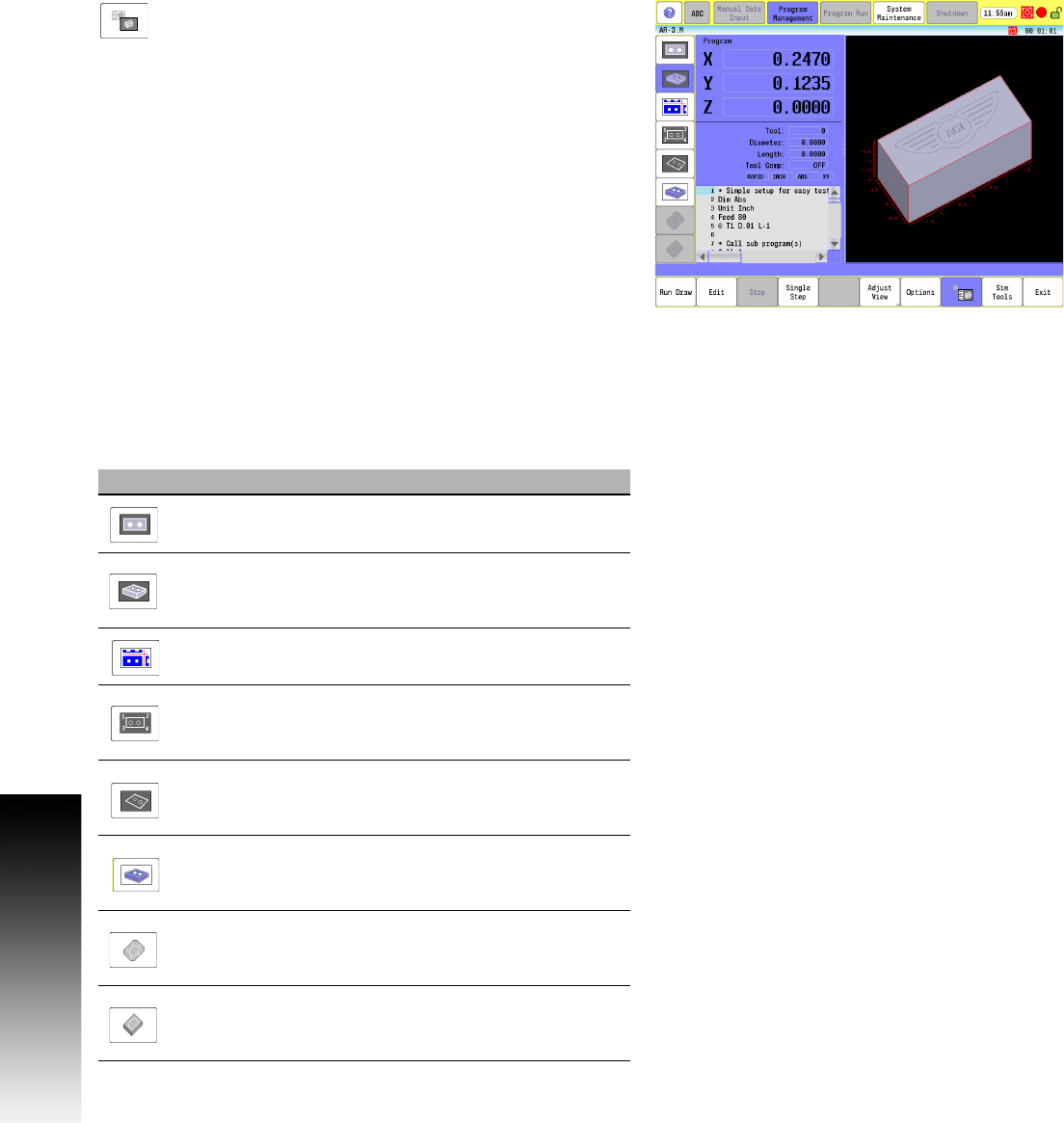
8.1 Draw
Touch the Display Program button to open the
program and dashboard screen.
View Options Menu
The Side Bar menu contains buttons to change the graphic view
modes and style. The following table describes these buttons.
Button Function
2D Top Plane Solid View is a two dimensional (2D)
top plane view of a solid block form model.
3D Solid View is a three dimensional (3D) view of a
solid block form model. Touch, drag preview to
change angle of view.
Projection View adjust the view form and cursor
features to blue print view.
2D Wire Frame Top View is a top two dimensional
(2D) top plane view shown as a wire frame, and
displays the tool path.
3D Wire Frame View is a three dimensional (3D)
view shown as a wire frame, and displays the tool
path. Touch, drag preview to change angle of view.
3D Shaded View is a three Dimensional (3D) Shaded
View of a solid block form model only available after
the program finishes drawing.
Contour View with Line Numbers enables/disables
visibility of program line numbers. Available with 2D,
and 3D wire frame views.
Program Contour View enables/disables display of
programmed contours. Available with 2D, and 3D
wire frame views.