
Manual


Table Of Contents
- Controls of the 3500i
- Manual Information
- Introduction
- Machining Fundamentals
- Manual Data Input
- Tool Management
- 4.1 Tool Table
- 4.2 Tool Data
- Program Management
- Conversational Editing
- Programming: Canned Cycles, sub-programs
- 7.1 Explaining Basic Cycles
- Round/Chamfer
- Rapid
- Line
- Arc
- Dwell:
- Plane Selection
- Reference Point Return:
- Fixture Offset (Work Coordinate System Select):
- Unit (Inch/MM)
- Dimension (Abs/Inc)
- Absolute Zero Set
- Block Form
- Temporary Path Tolerance
- System Data
- FeedRate
- FeedRate (4th-Axis)
- Spindle RPM
- M - Functions
- Tool Definition and Activation
- Repeat Blocks
- 7.2 Canned Cycles
- 7.3 Probing Cycles
- 7.4 Sub-programs
- 7.1 Explaining Basic Cycles
- Drawing Programs
- Running a Program on the Machine
- CAM: Programming
- 10.1 CAM Programming
- CAM Mode
- Recommended CAM Programming Sequence
- CAM Mode Mouse Operations
- CAM Mode Screen
- Activating CAM Mode
- Creating a New Program
- Tool Path Data Input
- Quick Coordinate Entry
- Job Setup: Basic tab
- Job Setup: Advanced tab
- Comment Tab
- Block Form: Basic tab
- Comment Tab
- Drilling Cycle:
- Drilling dialogue:
- Mill Cycle
- Pocket Cycle
- Pocket Finish Cycles
- Engraving Cycle
- Program Directive
- Modifying Toolbar
- Viewing Tools
- CAM Mode buttons
- CAM Setup
- Geometry
- DXF Import Feature
- Modifying Tools
- Shapes
- Tool Table
- Tool Paths
- CAM Example 1
- CAM Example 2
- 10.1 CAM Programming
- G-Code Edit, Help, & Advanced Features
- 11.1 G-Code Program Editing
- 11.2 G-Code and M-Code Definitions
- 11.3 Edit Help
- 11.4 Advanced Programming
- SPEED
- M - Functions
- Order of Execution
- Programming Non-modal Exact Stop:
- In-Position Mode (Exact Stop Check):
- Contouring Mode (Cutting Mode) :
- Setting Stroke Limit:
- Return from Reference Point:
- Move Reference from Machine Datum:
- Modifiers
- Block Separators
- Tool Offset Modification
- Expressions and Functions
- System Variables
- User Variables
- Variable Programming (Parametric Programming)
- Probe Move (G31)
- Conditional Statements
- Short Form Addressing
- Logical and Comparative Terms
- File Inclusion
- 11.5 Four Axis Programming
- Software Update
- Off-Line Software
ACU-RITE 3500i 257
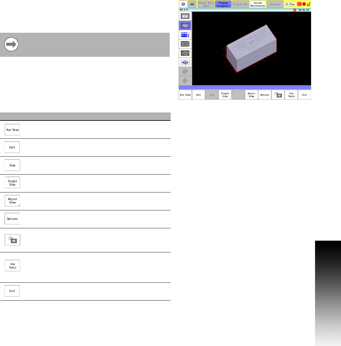
8.1 Draw
Starting Draw
Draw Simulation Mode is started from the Program Manager. You
can make some changes from the buttons while a simulation is
running. In Draw Simulation Mode, the 3500i does not hold the
operation of the program for Dwells and tool mounts and other
machine related features.
Any button that is grayed out indicates that feature is not available
in the selected view.
In the Program Manager, highlight a program and touch the Draw
button on the bottom menu bar. The Draw graphic screen activates,
and the program simulation starts.
BlockForm (G120) must be defined in the program that is
using Draw and a tool with a diameter defined must be
active in the program for Draw to work.
Button Function
Run Draw runs the program and starts the Draw
Simulation Mode.
Press Edit to edit the program.
Pressing Stop will stop the program.
Single Step executes the program one block at a
time; press Run Draw after each block.
Adjust View provides a new button menu with
options for altering the graphic view characteristics.
Options opens the Options dialogue.
Show/Hide dashboard: Toggles the graphic view
area to display the program and the position
dashboard, in addition to the graphic view.
Sim Tools displays the Simulation Tools table. The
Simulation Tool Table stores tool diameter, length
offsets and wear factors for tools used in Draw
Simulation Mode.
Exit will return to the Program Manager.