
Manual


Table Of Contents
- Controls of the 3500i
- Manual Information
- Introduction
- Machining Fundamentals
- Manual Data Input
- Tool Management
- 4.1 Tool Table
- 4.2 Tool Data
- Program Management
- Conversational Editing
- Programming: Canned Cycles, sub-programs
- 7.1 Explaining Basic Cycles
- Round/Chamfer
- Rapid
- Line
- Arc
- Dwell:
- Plane Selection
- Reference Point Return:
- Fixture Offset (Work Coordinate System Select):
- Unit (Inch/MM)
- Dimension (Abs/Inc)
- Absolute Zero Set
- Block Form
- Temporary Path Tolerance
- System Data
- FeedRate
- FeedRate (4th-Axis)
- Spindle RPM
- M - Functions
- Tool Definition and Activation
- Repeat Blocks
- 7.2 Canned Cycles
- 7.3 Probing Cycles
- 7.4 Sub-programs
- 7.1 Explaining Basic Cycles
- Drawing Programs
- Running a Program on the Machine
- CAM: Programming
- 10.1 CAM Programming
- CAM Mode
- Recommended CAM Programming Sequence
- CAM Mode Mouse Operations
- CAM Mode Screen
- Activating CAM Mode
- Creating a New Program
- Tool Path Data Input
- Quick Coordinate Entry
- Job Setup: Basic tab
- Job Setup: Advanced tab
- Comment Tab
- Block Form: Basic tab
- Comment Tab
- Drilling Cycle:
- Drilling dialogue:
- Mill Cycle
- Pocket Cycle
- Pocket Finish Cycles
- Engraving Cycle
- Program Directive
- Modifying Toolbar
- Viewing Tools
- CAM Mode buttons
- CAM Setup
- Geometry
- DXF Import Feature
- Modifying Tools
- Shapes
- Tool Table
- Tool Paths
- CAM Example 1
- CAM Example 2
- 10.1 CAM Programming
- G-Code Edit, Help, & Advanced Features
- 11.1 G-Code Program Editing
- 11.2 G-Code and M-Code Definitions
- 11.3 Edit Help
- 11.4 Advanced Programming
- SPEED
- M - Functions
- Order of Execution
- Programming Non-modal Exact Stop:
- In-Position Mode (Exact Stop Check):
- Contouring Mode (Cutting Mode) :
- Setting Stroke Limit:
- Return from Reference Point:
- Move Reference from Machine Datum:
- Modifiers
- Block Separators
- Tool Offset Modification
- Expressions and Functions
- System Variables
- User Variables
- Variable Programming (Parametric Programming)
- Probe Move (G31)
- Conditional Statements
- Short Form Addressing
- Logical and Comparative Terms
- File Inclusion
- 11.5 Four Axis Programming
- Software Update
- Off-Line Software
ACU-RITE 3500i 239
7.4 Sub-programs
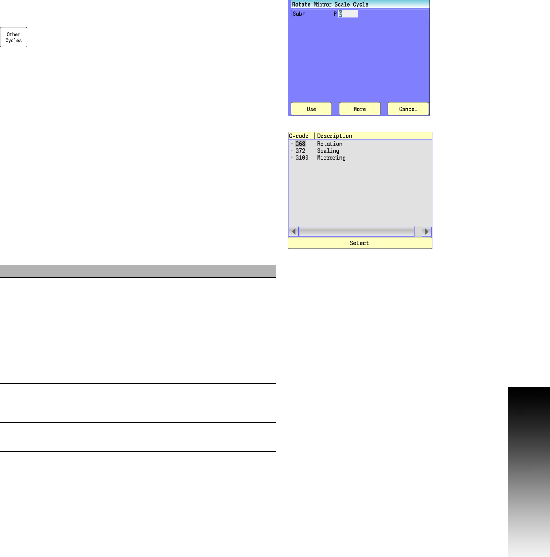
Rotate, Mirror, and/or Scale a sub-program
Use RMS blocks to Rotate, Mirror, and/or Scale sub-programs. These
functions turn off when the sub-program ends.
Select "Other Cycles" and then "RMS" from the pop-up
menu.
Conversational format: RMS
Patterns commanded by the program can be rotated using polar
coordinates. Any angle can be described as positive or negative,
depending on how it is referenced. CCW from 0 degrees is positive.
CW from 0 degrees is negative.
G-code formats: G68
Mirroring reverses the sign (+/-) of subsequent numbers and
movements, resulting in a reflection of the original pattern.
G-code formats: G100
Use Scaling to enlarge or reduce patterns commanded by the
program. If a variable word is not given, it is assumed to be x1 factor.
Axes for circular motion must have the same factor.
Tool length offsets, diameter offsets, tool wear factors, and tool
diameter compensation are not affected by scaling.
G-code format: G72
Field Code Description
Sub# P The number designation of the
sub-program to be used. (required)
#Loops M The number of times the sub-program will
execute before returning back to the main
program.
StartAngle F Polar degree angle which the pattern will
rotate for the first Loop. Defaults to same
as Angle.
Angle C Polar degree angle which the pattern will
rotate for the remaining Loops. Defaults to
same as StartAngle.
XCenter I X-Axis coordinate for the point of rotation,
the point about which rotation occurs.
YCenter J Y-Axis coordinate for the point of rotation,
the point about which rotation occurs.