
Manual


Table Of Contents
- Controls of the 3500i
- Manual Information
- Introduction
- Machining Fundamentals
- Manual Data Input
- Tool Management
- 4.1 Tool Table
- 4.2 Tool Data
- Program Management
- Conversational Editing
- Programming: Canned Cycles, sub-programs
- 7.1 Explaining Basic Cycles
- Round/Chamfer
- Rapid
- Line
- Arc
- Dwell:
- Plane Selection
- Reference Point Return:
- Fixture Offset (Work Coordinate System Select):
- Unit (Inch/MM)
- Dimension (Abs/Inc)
- Absolute Zero Set
- Block Form
- Temporary Path Tolerance
- System Data
- FeedRate
- FeedRate (4th-Axis)
- Spindle RPM
- M - Functions
- Tool Definition and Activation
- Repeat Blocks
- 7.2 Canned Cycles
- 7.3 Probing Cycles
- 7.4 Sub-programs
- 7.1 Explaining Basic Cycles
- Drawing Programs
- Running a Program on the Machine
- CAM: Programming
- 10.1 CAM Programming
- CAM Mode
- Recommended CAM Programming Sequence
- CAM Mode Mouse Operations
- CAM Mode Screen
- Activating CAM Mode
- Creating a New Program
- Tool Path Data Input
- Quick Coordinate Entry
- Job Setup: Basic tab
- Job Setup: Advanced tab
- Comment Tab
- Block Form: Basic tab
- Comment Tab
- Drilling Cycle:
- Drilling dialogue:
- Mill Cycle
- Pocket Cycle
- Pocket Finish Cycles
- Engraving Cycle
- Program Directive
- Modifying Toolbar
- Viewing Tools
- CAM Mode buttons
- CAM Setup
- Geometry
- DXF Import Feature
- Modifying Tools
- Shapes
- Tool Table
- Tool Paths
- CAM Example 1
- CAM Example 2
- 10.1 CAM Programming
- G-Code Edit, Help, & Advanced Features
- 11.1 G-Code Program Editing
- 11.2 G-Code and M-Code Definitions
- 11.3 Edit Help
- 11.4 Advanced Programming
- SPEED
- M - Functions
- Order of Execution
- Programming Non-modal Exact Stop:
- In-Position Mode (Exact Stop Check):
- Contouring Mode (Cutting Mode) :
- Setting Stroke Limit:
- Return from Reference Point:
- Move Reference from Machine Datum:
- Modifiers
- Block Separators
- Tool Offset Modification
- Expressions and Functions
- System Variables
- User Variables
- Variable Programming (Parametric Programming)
- Probe Move (G31)
- Conditional Statements
- Short Form Addressing
- Logical and Comparative Terms
- File Inclusion
- 11.5 Four Axis Programming
- Software Update
- Off-Line Software
232 7 Programming: Canned Cycles, sub-programs
7.3 Probing Cycles
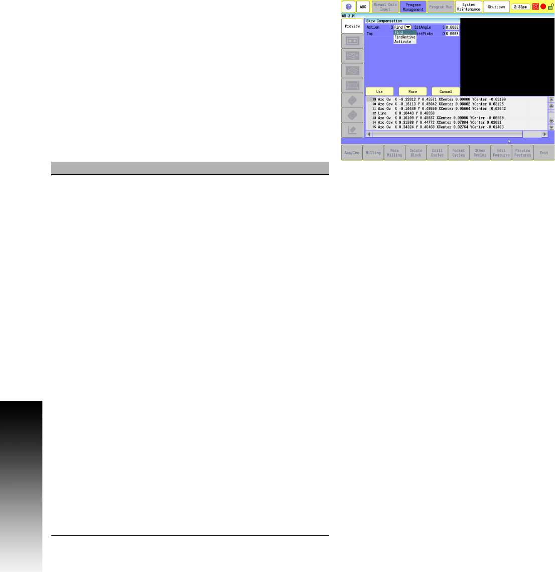
Skew Compensation
G68, axis rotation, cannot be used with skew compensation find.
Skew compensation is only supported for along the side edge of a
part relative to the X,Y plane. Skew compensation is only supported
for along the side edge of a part relative to the X,Y plane.
Calibrate the work probe at least once before trying to use this cycle.
A preliminary tool-length offset must be set by eye for the work
probe. The tool offset, and work coordinate must be active before
using this cycle in a program. See Section 4, "Tool-Length Offsets"
on page 73.
The probe must be pre-positioned to the proper spot in relation to
the part in accordance with the specified S parameter as described
below or an I, J, and/or K should be included for pre-positioning.
The Skew compensation Finding Cycle can be run from within a
program or from the Manual Data Input Mode .
Field Code Description
Action Q Q0 Finds the skew angle, but does not
activate skew compensation.
Q1 Finds the skew angle, and activates
skew compensation.
Q2 Activates skew compensation with the
current skew value, but does not rerun the
cycle on the part.
If Q2 is used, all other skew compensation
parameters are ignored.
Before using skew compensation Q2, you
must have called skew compensation at
least once with Q0 or Q1, or the error
message "Skew Compensation has not
been found!" is displayed.
Skew compensation is activated around the
current active work coordinate and only
works from within the program being run.
Skew compensation cannot be activated
directly or indirectly using skew
compensation from the MDI mode.
The operator can run the skew
compensation from MDI but must place
skew compensation Q2 inside the program
for skew compensation to take effect.
A G53 work coordinate call deactivates
skew compensation, necessitating a
re-issuance of skew compensation Q2 to
activate skew compensation.
Using Q1 or Q2 defaults the control to G90
(Absolute). If you are in G91 (Incremental),
you need to switch back after the cycle has
been run. (Optional)