
Manual


Table Of Contents
- Controls of the 3500i
- Manual Information
- Introduction
- Machining Fundamentals
- Manual Data Input
- Tool Management
- 4.1 Tool Table
- 4.2 Tool Data
- Program Management
- Conversational Editing
- Programming: Canned Cycles, sub-programs
- 7.1 Explaining Basic Cycles
- Round/Chamfer
- Rapid
- Line
- Arc
- Dwell:
- Plane Selection
- Reference Point Return:
- Fixture Offset (Work Coordinate System Select):
- Unit (Inch/MM)
- Dimension (Abs/Inc)
- Absolute Zero Set
- Block Form
- Temporary Path Tolerance
- System Data
- FeedRate
- FeedRate (4th-Axis)
- Spindle RPM
- M - Functions
- Tool Definition and Activation
- Repeat Blocks
- 7.2 Canned Cycles
- 7.3 Probing Cycles
- 7.4 Sub-programs
- 7.1 Explaining Basic Cycles
- Drawing Programs
- Running a Program on the Machine
- CAM: Programming
- 10.1 CAM Programming
- CAM Mode
- Recommended CAM Programming Sequence
- CAM Mode Mouse Operations
- CAM Mode Screen
- Activating CAM Mode
- Creating a New Program
- Tool Path Data Input
- Quick Coordinate Entry
- Job Setup: Basic tab
- Job Setup: Advanced tab
- Comment Tab
- Block Form: Basic tab
- Comment Tab
- Drilling Cycle:
- Drilling dialogue:
- Mill Cycle
- Pocket Cycle
- Pocket Finish Cycles
- Engraving Cycle
- Program Directive
- Modifying Toolbar
- Viewing Tools
- CAM Mode buttons
- CAM Setup
- Geometry
- DXF Import Feature
- Modifying Tools
- Shapes
- Tool Table
- Tool Paths
- CAM Example 1
- CAM Example 2
- 10.1 CAM Programming
- G-Code Edit, Help, & Advanced Features
- 11.1 G-Code Program Editing
- 11.2 G-Code and M-Code Definitions
- 11.3 Edit Help
- 11.4 Advanced Programming
- SPEED
- M - Functions
- Order of Execution
- Programming Non-modal Exact Stop:
- In-Position Mode (Exact Stop Check):
- Contouring Mode (Cutting Mode) :
- Setting Stroke Limit:
- Return from Reference Point:
- Move Reference from Machine Datum:
- Modifiers
- Block Separators
- Tool Offset Modification
- Expressions and Functions
- System Variables
- User Variables
- Variable Programming (Parametric Programming)
- Probe Move (G31)
- Conditional Statements
- Short Form Addressing
- Logical and Comparative Terms
- File Inclusion
- 11.5 Four Axis Programming
- Software Update
- Off-Line Software
ACU-RITE 3500i 223
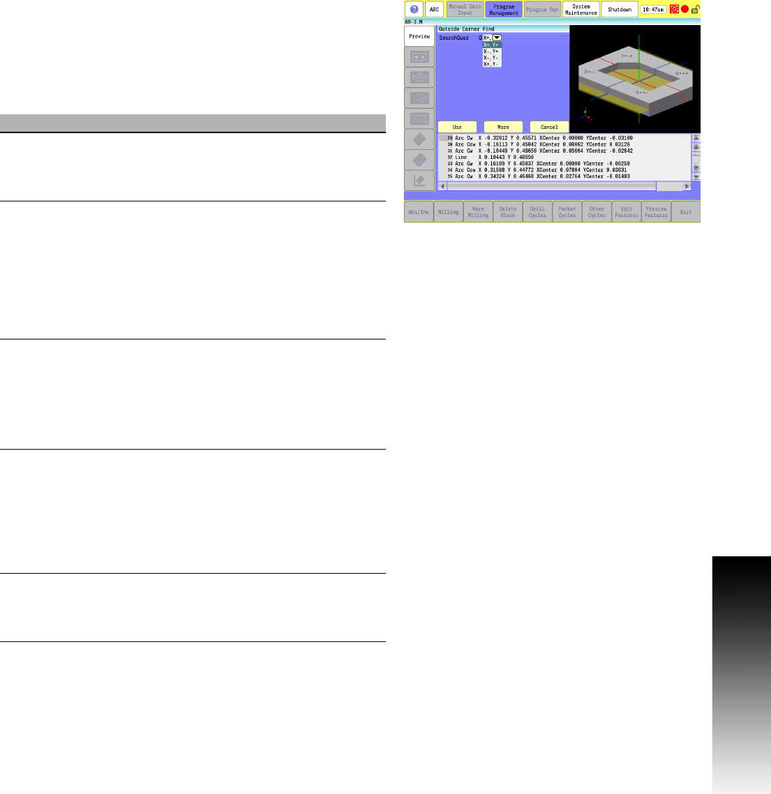
7.3 Probing Cycles
Outside Corner Finding
Calibrate the work probe at least once before trying to use this cycle.
A preliminary tool-length offset must be set by eye for the work
probe. The tool offset, and work coordinate must be active before
using this cycle in a program. See Section 4, "Tool-Length Offsets"
on page 73.
The Outside Corner Finding Cycle can be run from within a program
or from the Manual Data Input Mode.
Field Code Description
Search
Quad
Q Quadrant of corner to find.
0 = +,+ (upper right) 1 = -,+ (upper left)
2 = -,- (lower left) 3 = +,- (lower right)
(Required)
Top H If set to 1, the cycle finds the top of the part
before finding the X & Y corner coordinate.
Default is: 0. If H is not set or is set to 0, the
Z-axis must be at the picking depth. If H =
1, then the Z-axis must be within 0.1" (2.54
mm) above the part. The probe stylus must
be positioned within 0.1" (2.54 mm) from
the outside of the corner in X & Y.
(Optional)
DistDown E The distance to go down from the top of
part to find X & Y coordinate of the corner.
This is only used if H parameter is set to 1.
Without any E value, the cycle brings the
probe stylus center down past the top of
the part after finding the top, 0.1" (2.54
mm). (Optional)
DistSide D The distance over from the corner to find X
& Y edge. This allows for a part corner that
has a large chamfer or radius where you
cannot pick the edge close to the
theoretical corner or has an obstruction
interfering with the default move. Default
is: 0.4" (10.16 mm).
(Optional)
DistBack V Specifies the distance away from the edge
for the probe to fast feed to before trying to
find it. Default is: 0.1"
(2.54 mm) if not set. (Optional)