
Manual


Table Of Contents
- Controls of the 3500i
- Manual Information
- Introduction
- Machining Fundamentals
- Manual Data Input
- Tool Management
- 4.1 Tool Table
- 4.2 Tool Data
- Program Management
- Conversational Editing
- Programming: Canned Cycles, sub-programs
- 7.1 Explaining Basic Cycles
- Round/Chamfer
- Rapid
- Line
- Arc
- Dwell:
- Plane Selection
- Reference Point Return:
- Fixture Offset (Work Coordinate System Select):
- Unit (Inch/MM)
- Dimension (Abs/Inc)
- Absolute Zero Set
- Block Form
- Temporary Path Tolerance
- System Data
- FeedRate
- FeedRate (4th-Axis)
- Spindle RPM
- M - Functions
- Tool Definition and Activation
- Repeat Blocks
- 7.2 Canned Cycles
- 7.3 Probing Cycles
- 7.4 Sub-programs
- 7.1 Explaining Basic Cycles
- Drawing Programs
- Running a Program on the Machine
- CAM: Programming
- 10.1 CAM Programming
- CAM Mode
- Recommended CAM Programming Sequence
- CAM Mode Mouse Operations
- CAM Mode Screen
- Activating CAM Mode
- Creating a New Program
- Tool Path Data Input
- Quick Coordinate Entry
- Job Setup: Basic tab
- Job Setup: Advanced tab
- Comment Tab
- Block Form: Basic tab
- Comment Tab
- Drilling Cycle:
- Drilling dialogue:
- Mill Cycle
- Pocket Cycle
- Pocket Finish Cycles
- Engraving Cycle
- Program Directive
- Modifying Toolbar
- Viewing Tools
- CAM Mode buttons
- CAM Setup
- Geometry
- DXF Import Feature
- Modifying Tools
- Shapes
- Tool Table
- Tool Paths
- CAM Example 1
- CAM Example 2
- 10.1 CAM Programming
- G-Code Edit, Help, & Advanced Features
- 11.1 G-Code Program Editing
- 11.2 G-Code and M-Code Definitions
- 11.3 Edit Help
- 11.4 Advanced Programming
- SPEED
- M - Functions
- Order of Execution
- Programming Non-modal Exact Stop:
- In-Position Mode (Exact Stop Check):
- Contouring Mode (Cutting Mode) :
- Setting Stroke Limit:
- Return from Reference Point:
- Move Reference from Machine Datum:
- Modifiers
- Block Separators
- Tool Offset Modification
- Expressions and Functions
- System Variables
- User Variables
- Variable Programming (Parametric Programming)
- Probe Move (G31)
- Conditional Statements
- Short Form Addressing
- Logical and Comparative Terms
- File Inclusion
- 11.5 Four Axis Programming
- Software Update
- Off-Line Software
222 7 Programming: Canned Cycles, sub-programs
7.3 Probing Cycles
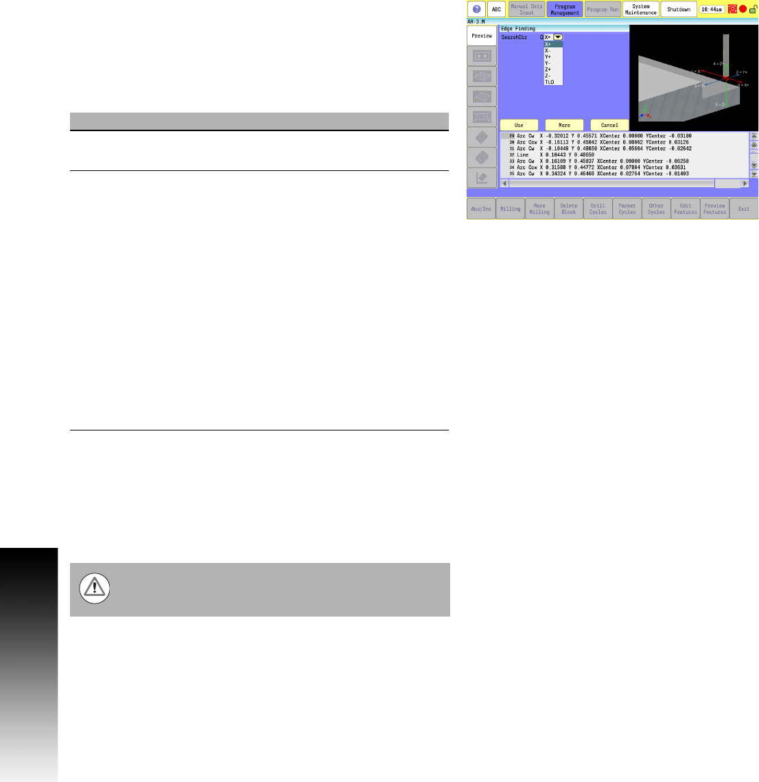
Edge Finding
Calibrate the work probe at least once before trying to use this cycle.
A preliminary tool-length offset must be set by eye for the work
probe and that tool offset, and work coordinate active before using
this cycle in a program. See Section 4, "Tool-Length Offsets" on page
73.
The Edge Finding Cycle can be run from within a program or from
Manual Data Input Mode.
To use the Edge Finding Cycle:
Place the probe in the spindle with its tool number active and the
tool type set to "Touch Probe".
Manually jog the probe stylus less than 0.1" (2.54 mm) away from
the surface to be found.
Type G141 Qn Wn. If this is run from inside a program, this line
needs to be repeated for every surface you wish to find.
Execute the line in Manual Data Input Mode by touching NC Start.
Field Code Description
Search
Dir
Q Axis and direction to find edge.
0 = X+, 1 = X-, 2 = Y+, 3 = Y-, 4 = Z+, 5 = Z-
Offset W Work Coordinate to update with edge
location in X- or:
Y-axes. If set, work coordinate is updated if
0 through 3 are specified for Q or Z work
offset (or TLO if
updateTloOrWorkOffsetZAxis is set to
TLO) if Q is set to 4 or 5 and Z TLO if Q is
set to 6.
Before any tool-length offset is active, you
must re-call that tool. Work coordinate
register or Tool-length register is not
updated if W is not set and a warning
message tells the operator no update has
taken place except when Q is set to 6 in
which case the Spindle Probe TLO will
always be reset. (Optional)
When positioning the probe from within the program you
should always use the G146 (Protected Probe Positioning)
cycle (see G146 instructions later in this document).