
Manual


Table Of Contents
- Controls of the 3500i
- Manual Information
- Introduction
- Machining Fundamentals
- Manual Data Input
- Tool Management
- 4.1 Tool Table
- 4.2 Tool Data
- Program Management
- Conversational Editing
- Programming: Canned Cycles, sub-programs
- 7.1 Explaining Basic Cycles
- Round/Chamfer
- Rapid
- Line
- Arc
- Dwell:
- Plane Selection
- Reference Point Return:
- Fixture Offset (Work Coordinate System Select):
- Unit (Inch/MM)
- Dimension (Abs/Inc)
- Absolute Zero Set
- Block Form
- Temporary Path Tolerance
- System Data
- FeedRate
- FeedRate (4th-Axis)
- Spindle RPM
- M - Functions
- Tool Definition and Activation
- Repeat Blocks
- 7.2 Canned Cycles
- 7.3 Probing Cycles
- 7.4 Sub-programs
- 7.1 Explaining Basic Cycles
- Drawing Programs
- Running a Program on the Machine
- CAM: Programming
- 10.1 CAM Programming
- CAM Mode
- Recommended CAM Programming Sequence
- CAM Mode Mouse Operations
- CAM Mode Screen
- Activating CAM Mode
- Creating a New Program
- Tool Path Data Input
- Quick Coordinate Entry
- Job Setup: Basic tab
- Job Setup: Advanced tab
- Comment Tab
- Block Form: Basic tab
- Comment Tab
- Drilling Cycle:
- Drilling dialogue:
- Mill Cycle
- Pocket Cycle
- Pocket Finish Cycles
- Engraving Cycle
- Program Directive
- Modifying Toolbar
- Viewing Tools
- CAM Mode buttons
- CAM Setup
- Geometry
- DXF Import Feature
- Modifying Tools
- Shapes
- Tool Table
- Tool Paths
- CAM Example 1
- CAM Example 2
- 10.1 CAM Programming
- G-Code Edit, Help, & Advanced Features
- 11.1 G-Code Program Editing
- 11.2 G-Code and M-Code Definitions
- 11.3 Edit Help
- 11.4 Advanced Programming
- SPEED
- M - Functions
- Order of Execution
- Programming Non-modal Exact Stop:
- In-Position Mode (Exact Stop Check):
- Contouring Mode (Cutting Mode) :
- Setting Stroke Limit:
- Return from Reference Point:
- Move Reference from Machine Datum:
- Modifiers
- Block Separators
- Tool Offset Modification
- Expressions and Functions
- System Variables
- User Variables
- Variable Programming (Parametric Programming)
- Probe Move (G31)
- Conditional Statements
- Short Form Addressing
- Logical and Comparative Terms
- File Inclusion
- 11.5 Four Axis Programming
- Software Update
- Off-Line Software
220 7 Programming: Canned Cycles, sub-programs
7.3 Probing Cycles
positioningFeedRate_Normally - set to the feedrate the control will
use while normally positioning the probe around the part
positioningFeedRate_FirstTouch - set to the feedrate the control will
use while making its initial touch to find the surface it is measuring.
dwellTimeAfterProbeActive - for wireless probes, set to the time to
wait after the probe is turned on before attempting a probe move, as
recommended by the probe manufacturer.
updateTloOrWorkOffsetZAxis - select whether to update the values
for the Tool Length Offset (TLO) or the Workpiece Offset
(WorkOffset).
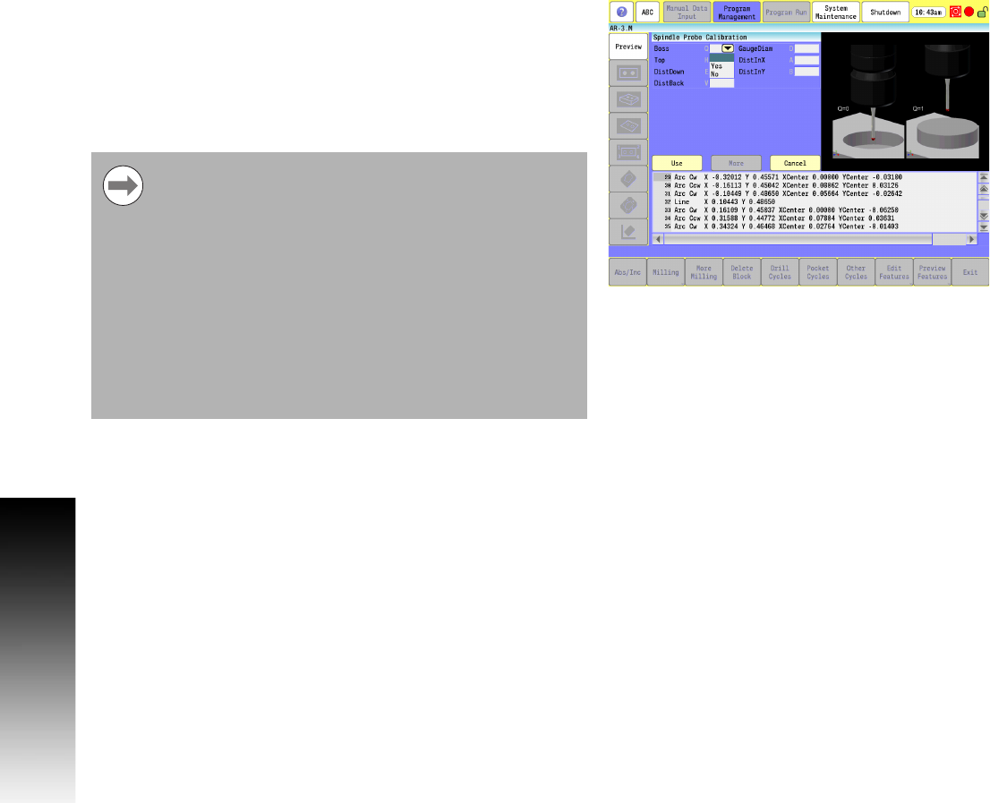
Spindle Probe Calibration Cycle
This is used to set the effective probe stylus diameter and set the
compensation factor for any run-out of the probe stylus.
You need to have already configured the spindle probe settings per
the previous section.
You also need to have the probe assigned to a Tool # in the Tool
Table, with its 'Type' set to 'Touch Probe', and have it
activate/mounted via a Tool Call.
On machines that do not have spindle orientation or if you
are using a corded probe or cordless UD probe and cannot
orient the spindle 180 degrees during calibration, the
spindle probe stylus needs to be indicated true to the
spindle centerline.
Also, before calibrating the probe with a wired type probe,
the center of spindle rotation must be indicated exactly
over the probe gauge center. In this case the accuracy of
the spindle probe is only as good as the stylus
concentricity to the spindle and the closeness to the probe
gauge center. Calibration must be done at least once
before using the spindle probe. Once calibrated,
calibration does not have to be done again unless you
replace the probe stylus.