
Manual


Table Of Contents
- Controls of the 3500i
- Manual Information
- Introduction
- Machining Fundamentals
- Manual Data Input
- Tool Management
- 4.1 Tool Table
- 4.2 Tool Data
- Program Management
- Conversational Editing
- Programming: Canned Cycles, sub-programs
- 7.1 Explaining Basic Cycles
- Round/Chamfer
- Rapid
- Line
- Arc
- Dwell:
- Plane Selection
- Reference Point Return:
- Fixture Offset (Work Coordinate System Select):
- Unit (Inch/MM)
- Dimension (Abs/Inc)
- Absolute Zero Set
- Block Form
- Temporary Path Tolerance
- System Data
- FeedRate
- FeedRate (4th-Axis)
- Spindle RPM
- M - Functions
- Tool Definition and Activation
- Repeat Blocks
- 7.2 Canned Cycles
- 7.3 Probing Cycles
- 7.4 Sub-programs
- 7.1 Explaining Basic Cycles
- Drawing Programs
- Running a Program on the Machine
- CAM: Programming
- 10.1 CAM Programming
- CAM Mode
- Recommended CAM Programming Sequence
- CAM Mode Mouse Operations
- CAM Mode Screen
- Activating CAM Mode
- Creating a New Program
- Tool Path Data Input
- Quick Coordinate Entry
- Job Setup: Basic tab
- Job Setup: Advanced tab
- Comment Tab
- Block Form: Basic tab
- Comment Tab
- Drilling Cycle:
- Drilling dialogue:
- Mill Cycle
- Pocket Cycle
- Pocket Finish Cycles
- Engraving Cycle
- Program Directive
- Modifying Toolbar
- Viewing Tools
- CAM Mode buttons
- CAM Setup
- Geometry
- DXF Import Feature
- Modifying Tools
- Shapes
- Tool Table
- Tool Paths
- CAM Example 1
- CAM Example 2
- 10.1 CAM Programming
- G-Code Edit, Help, & Advanced Features
- 11.1 G-Code Program Editing
- 11.2 G-Code and M-Code Definitions
- 11.3 Edit Help
- 11.4 Advanced Programming
- SPEED
- M - Functions
- Order of Execution
- Programming Non-modal Exact Stop:
- In-Position Mode (Exact Stop Check):
- Contouring Mode (Cutting Mode) :
- Setting Stroke Limit:
- Return from Reference Point:
- Move Reference from Machine Datum:
- Modifiers
- Block Separators
- Tool Offset Modification
- Expressions and Functions
- System Variables
- User Variables
- Variable Programming (Parametric Programming)
- Probe Move (G31)
- Conditional Statements
- Short Form Addressing
- Logical and Comparative Terms
- File Inclusion
- 11.5 Four Axis Programming
- Software Update
- Off-Line Software
216 7 Programming: Canned Cycles, sub-programs
7.3 Probing Cycles
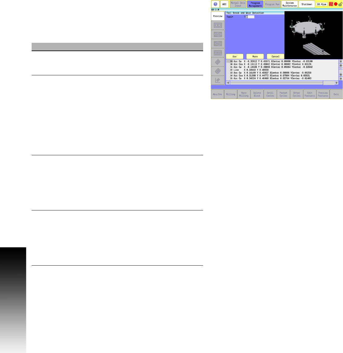
Tool Breakage, Length and Diameter Wear Detection
Checks the tool and gives an alarm if not within tolerance. Length
and Diameter Wear - Check the Length and/or Diameter and
updates the Length and/or Diameter wear registers up to a
user-defined limit. Once the user-defined limit has been reached,
the cycle gives an alarm and the program stops.
Field Code Description
Tool# T Tool number. (Required)
The T cycle parameter is the tool number
you want checked.
EstDiam D This is the rough diameter on the bottom of
the tool. (Optional)
The diameter specified in this parameter
should be roughly the diameter on the
bottom of the tool that you want to be over
the center of the probe stylus. If you have a
left-handed tool, you would give a negative
value to this diameter so the spindle turns
on forward verses reverse. When stepping
over for checking the diameter of the tool,
this cycle uses the diameter in the tool table
for the tool being checked.
MaxLen
Adj
K The maximum length wear value limit. The
cycle checks to see if the cutter length has
changed by more than this amount and
triggers the alarm, stopping the program if
exceeded. If not set, the cycle does not
check the tool length. (Optional)
At least one, K or J must be set or the cycle
alarms.
MaxDia
Adj
J The maximum diameter wear value limit.
The cycle checks to see if the cutter
diameter has changed by more than this
amount and alarms, stopping the program if
exceeded. If not set, the cycle does not
check the tool diameter. (Optional)
At least one, K or J must be set or the cycle
alarms.