
Manual


Table Of Contents
- Controls of the 3500i
- Manual Information
- Introduction
- Machining Fundamentals
- Manual Data Input
- Tool Management
- 4.1 Tool Table
- 4.2 Tool Data
- Program Management
- Conversational Editing
- Programming: Canned Cycles, sub-programs
- 7.1 Explaining Basic Cycles
- Round/Chamfer
- Rapid
- Line
- Arc
- Dwell:
- Plane Selection
- Reference Point Return:
- Fixture Offset (Work Coordinate System Select):
- Unit (Inch/MM)
- Dimension (Abs/Inc)
- Absolute Zero Set
- Block Form
- Temporary Path Tolerance
- System Data
- FeedRate
- FeedRate (4th-Axis)
- Spindle RPM
- M - Functions
- Tool Definition and Activation
- Repeat Blocks
- 7.2 Canned Cycles
- 7.3 Probing Cycles
- 7.4 Sub-programs
- 7.1 Explaining Basic Cycles
- Drawing Programs
- Running a Program on the Machine
- CAM: Programming
- 10.1 CAM Programming
- CAM Mode
- Recommended CAM Programming Sequence
- CAM Mode Mouse Operations
- CAM Mode Screen
- Activating CAM Mode
- Creating a New Program
- Tool Path Data Input
- Quick Coordinate Entry
- Job Setup: Basic tab
- Job Setup: Advanced tab
- Comment Tab
- Block Form: Basic tab
- Comment Tab
- Drilling Cycle:
- Drilling dialogue:
- Mill Cycle
- Pocket Cycle
- Pocket Finish Cycles
- Engraving Cycle
- Program Directive
- Modifying Toolbar
- Viewing Tools
- CAM Mode buttons
- CAM Setup
- Geometry
- DXF Import Feature
- Modifying Tools
- Shapes
- Tool Table
- Tool Paths
- CAM Example 1
- CAM Example 2
- 10.1 CAM Programming
- G-Code Edit, Help, & Advanced Features
- 11.1 G-Code Program Editing
- 11.2 G-Code and M-Code Definitions
- 11.3 Edit Help
- 11.4 Advanced Programming
- SPEED
- M - Functions
- Order of Execution
- Programming Non-modal Exact Stop:
- In-Position Mode (Exact Stop Check):
- Contouring Mode (Cutting Mode) :
- Setting Stroke Limit:
- Return from Reference Point:
- Move Reference from Machine Datum:
- Modifiers
- Block Separators
- Tool Offset Modification
- Expressions and Functions
- System Variables
- User Variables
- Variable Programming (Parametric Programming)
- Probe Move (G31)
- Conditional Statements
- Short Form Addressing
- Logical and Comparative Terms
- File Inclusion
- 11.5 Four Axis Programming
- Software Update
- Off-Line Software
ACU-RITE 3500i 213
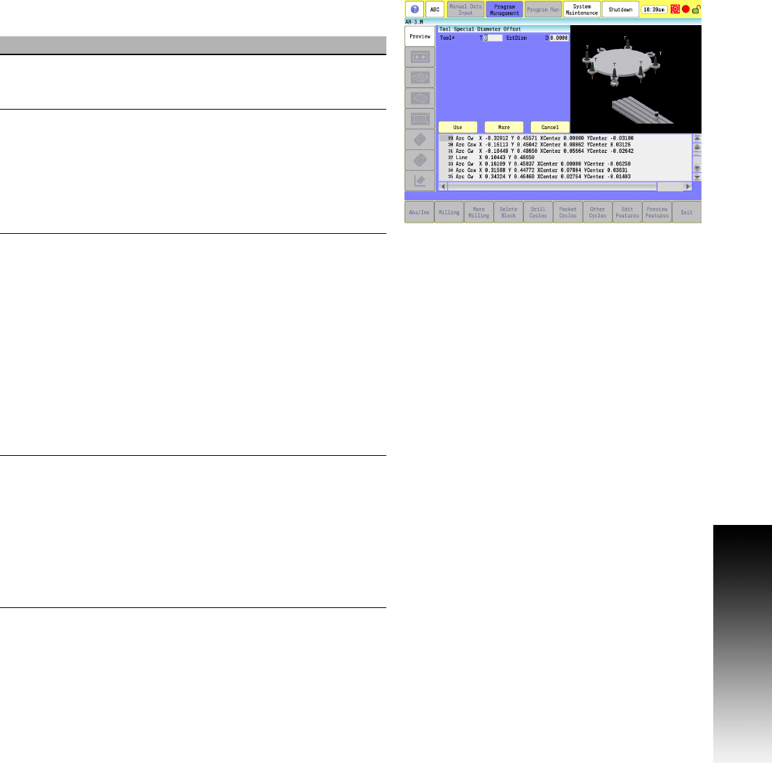
7.3 Probing Cycles
Manual Tool Diameter Measure for Special Tools
Updates tool diameter register for irregular shaped tools or tools
with a hole in the center of the bottom.
This cycle is used to measure the diameter of irregularly shaped tools
or tools with a hole in the center of the bottom.
Field Code Description
Tool# T Tool number. (Required)
The T cycle parameter must be the same as
the current tool in the spindle.
EstDiam D This is the rough diameter of the tool.
(Required) The diameter specified in this
cycle parameter should be larger than the
actual diameter of the tool being measured
but no more than 0.04" (1.0 mm) over. If
you have a left-handed tool, you would give
a negative value to the diameter so the
spindle turns on in the forward direction.
DistDown E The incremental distance from the current
Z Retract amount to go down along the side
of the probe stylus when doing a diameter
pick. The maximum E value is 0.55" (13.97
mm) or the tool may crash into the probe or
table. If you enter a value larger than 0.55"
(13.97 mm), the control issues an error
message. If E is not set, the cycle uses a
default value of 0.1" (2.54 mm). (Optional)
[Default: 0.1"]
Ball nose cutters and special cutters that
require a move down more than 0.55"
(13.97 mm) are not supported.
NOTE: Z Retract Amount is set in the Tool
Probe Parameters.
OvrMed
Feed
M This is the override for the medium
feedrate that was set in the machine setup
parameter ZFirstPickFeedRate_Medium.
Sometimes there may be a tool that has a
large diameter making it necessary to slow
it down to prevent the touch probe from
being hit too hard. This can only be set
slower. Trying to set this higher will result
in the software using the original feedrate.
(Optional)