
Manual


Table Of Contents
- Controls of the 3500i
- Manual Information
- Introduction
- Machining Fundamentals
- Manual Data Input
- Tool Management
- 4.1 Tool Table
- 4.2 Tool Data
- Program Management
- Conversational Editing
- Programming: Canned Cycles, sub-programs
- 7.1 Explaining Basic Cycles
- Round/Chamfer
- Rapid
- Line
- Arc
- Dwell:
- Plane Selection
- Reference Point Return:
- Fixture Offset (Work Coordinate System Select):
- Unit (Inch/MM)
- Dimension (Abs/Inc)
- Absolute Zero Set
- Block Form
- Temporary Path Tolerance
- System Data
- FeedRate
- FeedRate (4th-Axis)
- Spindle RPM
- M - Functions
- Tool Definition and Activation
- Repeat Blocks
- 7.2 Canned Cycles
- 7.3 Probing Cycles
- 7.4 Sub-programs
- 7.1 Explaining Basic Cycles
- Drawing Programs
- Running a Program on the Machine
- CAM: Programming
- 10.1 CAM Programming
- CAM Mode
- Recommended CAM Programming Sequence
- CAM Mode Mouse Operations
- CAM Mode Screen
- Activating CAM Mode
- Creating a New Program
- Tool Path Data Input
- Quick Coordinate Entry
- Job Setup: Basic tab
- Job Setup: Advanced tab
- Comment Tab
- Block Form: Basic tab
- Comment Tab
- Drilling Cycle:
- Drilling dialogue:
- Mill Cycle
- Pocket Cycle
- Pocket Finish Cycles
- Engraving Cycle
- Program Directive
- Modifying Toolbar
- Viewing Tools
- CAM Mode buttons
- CAM Setup
- Geometry
- DXF Import Feature
- Modifying Tools
- Shapes
- Tool Table
- Tool Paths
- CAM Example 1
- CAM Example 2
- 10.1 CAM Programming
- G-Code Edit, Help, & Advanced Features
- 11.1 G-Code Program Editing
- 11.2 G-Code and M-Code Definitions
- 11.3 Edit Help
- 11.4 Advanced Programming
- SPEED
- M - Functions
- Order of Execution
- Programming Non-modal Exact Stop:
- In-Position Mode (Exact Stop Check):
- Contouring Mode (Cutting Mode) :
- Setting Stroke Limit:
- Return from Reference Point:
- Move Reference from Machine Datum:
- Modifiers
- Block Separators
- Tool Offset Modification
- Expressions and Functions
- System Variables
- User Variables
- Variable Programming (Parametric Programming)
- Probe Move (G31)
- Conditional Statements
- Short Form Addressing
- Logical and Comparative Terms
- File Inclusion
- 11.5 Four Axis Programming
- Software Update
- Off-Line Software
ACU-RITE 3500i 201
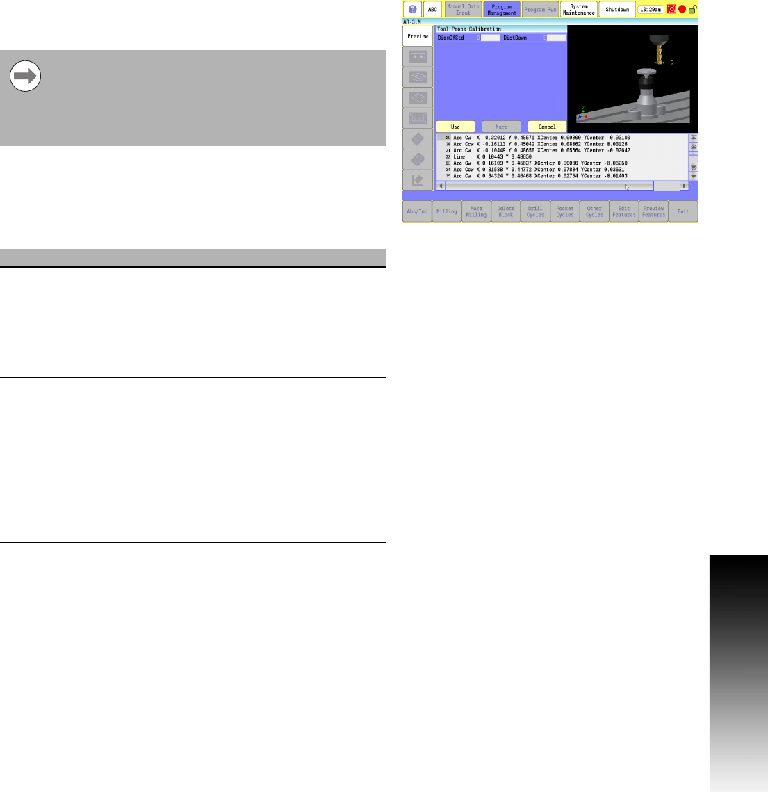
7.3 Probing Cycles
Tool Probe Calibration Cycle
This is used to set the Z datum for length preset, the effective probe
stylus diameter for setting tool diameter registers, and establishes
the center of the probe stylus.
This cycle is used to calibrate the probe. This is used to set the Z
datum for length preset, establishing the center of the probe stylus,
and the effective probe stylus diameter for setting tool diameter
registers.
Calibration must be done at least once before using the
tool probe. Once the probe has been calibrated, calibration
does not need to be done again unless the probe is moved
or a new part is being setup. The cycle must always know
the relationship between the top of the part and the top of
the probe to set the TLO.
Field Code Description
DiamOfStd D The diameter of the part of the calibration
standard that comes in contact with the
probe stylus during calibration. This should
be an exact measurement. (Optional)
override for the
DiameterOfToolProbeGauge machine
setup parameter) .
DistDown E The incremental distance from the current Z
Retract amount to go down along the side
of the probe stylus when doing a diameter
pick. The maximum E value is 0.55" (13.97
mm) or the tool may crash into the probe or
table. If you enter a value larger than 0.55"
(13.97 mm), the control issues an error
message. If E is not set, the cycle uses a
default value of 0.1" (2.54 mm). (Optional)
[Default: 0.1"]. Z Retract Amount is set in
the Tool Probe Parameters.