
Manual


Table Of Contents
- Controls of the 3500i
- Manual Information
- Introduction
- Machining Fundamentals
- Manual Data Input
- Tool Management
- 4.1 Tool Table
- 4.2 Tool Data
- Program Management
- Conversational Editing
- Programming: Canned Cycles, sub-programs
- 7.1 Explaining Basic Cycles
- Round/Chamfer
- Rapid
- Line
- Arc
- Dwell:
- Plane Selection
- Reference Point Return:
- Fixture Offset (Work Coordinate System Select):
- Unit (Inch/MM)
- Dimension (Abs/Inc)
- Absolute Zero Set
- Block Form
- Temporary Path Tolerance
- System Data
- FeedRate
- FeedRate (4th-Axis)
- Spindle RPM
- M - Functions
- Tool Definition and Activation
- Repeat Blocks
- 7.2 Canned Cycles
- 7.3 Probing Cycles
- 7.4 Sub-programs
- 7.1 Explaining Basic Cycles
- Drawing Programs
- Running a Program on the Machine
- CAM: Programming
- 10.1 CAM Programming
- CAM Mode
- Recommended CAM Programming Sequence
- CAM Mode Mouse Operations
- CAM Mode Screen
- Activating CAM Mode
- Creating a New Program
- Tool Path Data Input
- Quick Coordinate Entry
- Job Setup: Basic tab
- Job Setup: Advanced tab
- Comment Tab
- Block Form: Basic tab
- Comment Tab
- Drilling Cycle:
- Drilling dialogue:
- Mill Cycle
- Pocket Cycle
- Pocket Finish Cycles
- Engraving Cycle
- Program Directive
- Modifying Toolbar
- Viewing Tools
- CAM Mode buttons
- CAM Setup
- Geometry
- DXF Import Feature
- Modifying Tools
- Shapes
- Tool Table
- Tool Paths
- CAM Example 1
- CAM Example 2
- 10.1 CAM Programming
- G-Code Edit, Help, & Advanced Features
- 11.1 G-Code Program Editing
- 11.2 G-Code and M-Code Definitions
- 11.3 Edit Help
- 11.4 Advanced Programming
- SPEED
- M - Functions
- Order of Execution
- Programming Non-modal Exact Stop:
- In-Position Mode (Exact Stop Check):
- Contouring Mode (Cutting Mode) :
- Setting Stroke Limit:
- Return from Reference Point:
- Move Reference from Machine Datum:
- Modifiers
- Block Separators
- Tool Offset Modification
- Expressions and Functions
- System Variables
- User Variables
- Variable Programming (Parametric Programming)
- Probe Move (G31)
- Conditional Statements
- Short Form Addressing
- Logical and Comparative Terms
- File Inclusion
- 11.5 Four Axis Programming
- Software Update
- Off-Line Software
ACU-RITE 3500i 197
7. 2 C a n n e d C y c l e s
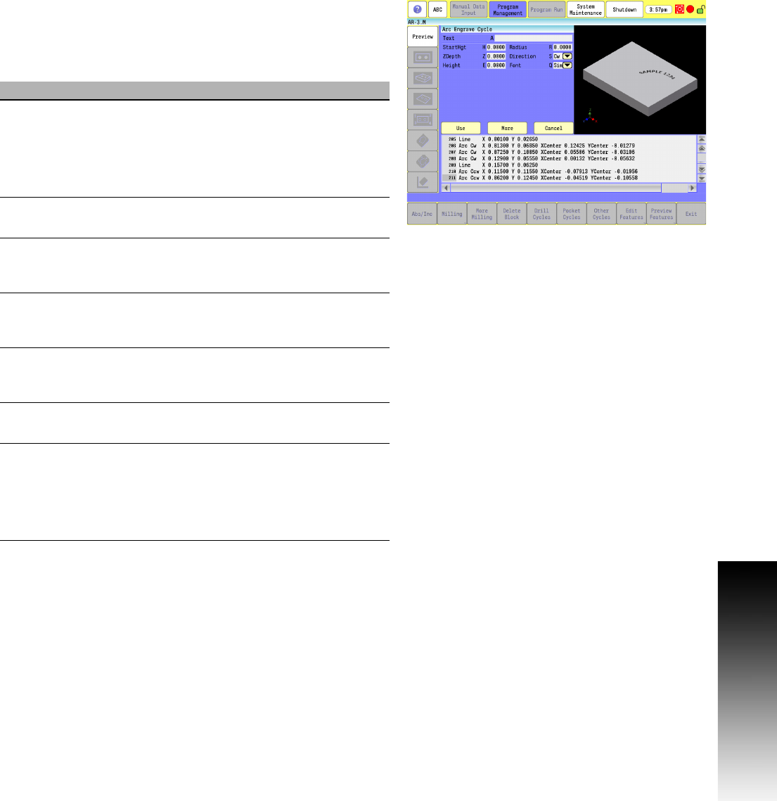
Programming the Arc Engrave Cycle
To program the Arc Engrave Cycle:
In Edit mode, touch Other Cycles, then touch Arc Engrave cycle to
display the Engrave Cycle menu.
Complete the entry fields, and touch USE.
Field Code Description
Text A Text string which is to be engraved. All
ASCII characters within the range of
x032 - x126 are allowed, which includes
Uppercase, Lowercase, Numbers, and
Punctuation (maximum 80 characters in
Text string). (Required)
StartHgt H Z absolute start height. Must be higher than
ZDepth (the "Z" parameter). (Required)
ZDepth Z Z absolute depth of engraving. Must be
below StartHgt (the "H" parameter).
(Required)
Height E Letter height. Width is proportional to
height. Height is measured at the centerline
of the cutter. (Required)
Radius R Radius of arc. Must be a positive integer.
For upward arc (CCW), include text Height
in calculation. (Required)
Direction S Arc direction, CCW (S=1) or CW (S=0).
Default is CW (S=0). (Required)
Font Q Font type to be used.
(Q1) Simple is a standard appearance.
(Q2) Stencil is a stenciled appearance.
(Q3) Stick has no rounded movements, only
straight moves. Default is Simple.
(Required)