
Manual


Table Of Contents
- Controls of the 3500i
- Manual Information
- Introduction
- Machining Fundamentals
- Manual Data Input
- Tool Management
- 4.1 Tool Table
- 4.2 Tool Data
- Program Management
- Conversational Editing
- Programming: Canned Cycles, sub-programs
- 7.1 Explaining Basic Cycles
- Round/Chamfer
- Rapid
- Line
- Arc
- Dwell:
- Plane Selection
- Reference Point Return:
- Fixture Offset (Work Coordinate System Select):
- Unit (Inch/MM)
- Dimension (Abs/Inc)
- Absolute Zero Set
- Block Form
- Temporary Path Tolerance
- System Data
- FeedRate
- FeedRate (4th-Axis)
- Spindle RPM
- M - Functions
- Tool Definition and Activation
- Repeat Blocks
- 7.2 Canned Cycles
- 7.3 Probing Cycles
- 7.4 Sub-programs
- 7.1 Explaining Basic Cycles
- Drawing Programs
- Running a Program on the Machine
- CAM: Programming
- 10.1 CAM Programming
- CAM Mode
- Recommended CAM Programming Sequence
- CAM Mode Mouse Operations
- CAM Mode Screen
- Activating CAM Mode
- Creating a New Program
- Tool Path Data Input
- Quick Coordinate Entry
- Job Setup: Basic tab
- Job Setup: Advanced tab
- Comment Tab
- Block Form: Basic tab
- Comment Tab
- Drilling Cycle:
- Drilling dialogue:
- Mill Cycle
- Pocket Cycle
- Pocket Finish Cycles
- Engraving Cycle
- Program Directive
- Modifying Toolbar
- Viewing Tools
- CAM Mode buttons
- CAM Setup
- Geometry
- DXF Import Feature
- Modifying Tools
- Shapes
- Tool Table
- Tool Paths
- CAM Example 1
- CAM Example 2
- 10.1 CAM Programming
- G-Code Edit, Help, & Advanced Features
- 11.1 G-Code Program Editing
- 11.2 G-Code and M-Code Definitions
- 11.3 Edit Help
- 11.4 Advanced Programming
- SPEED
- M - Functions
- Order of Execution
- Programming Non-modal Exact Stop:
- In-Position Mode (Exact Stop Check):
- Contouring Mode (Cutting Mode) :
- Setting Stroke Limit:
- Return from Reference Point:
- Move Reference from Machine Datum:
- Modifiers
- Block Separators
- Tool Offset Modification
- Expressions and Functions
- System Variables
- User Variables
- Variable Programming (Parametric Programming)
- Probe Move (G31)
- Conditional Statements
- Short Form Addressing
- Logical and Comparative Terms
- File Inclusion
- 11.5 Four Axis Programming
- Software Update
- Off-Line Software
ACU-RITE 3500i 195
7. 2 C a n n e d C y c l e s
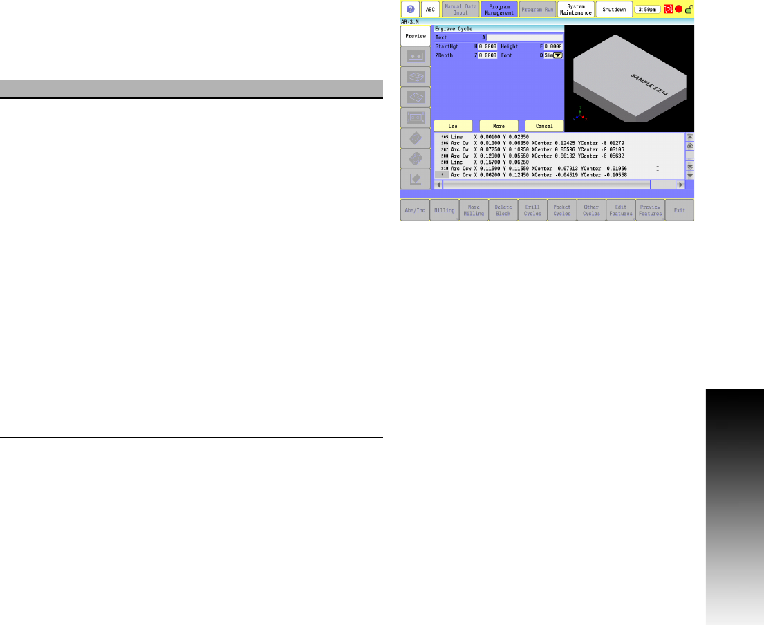
Engraving Cycles
Engraving cycles provides a quick and easy way to engrave part
numbers, legends, or any alpha/numeric inscription. The usual type of
cutter is a sharp point or center drill type tool. Options are given for
engraving on an angle (G190), rotating by a certain angle (G191) and
mirror is supported for engraving molds.
When executed, the CNC rapids to the start point, then to the
StartHgt (the "H" parameter). It then feeds to the ZDepth (the "Z"
parameter) specified and begins cutting the Text selected.
Programming the Engrave Cycle
To program the Engrave Cycle:
In Edit mode, touch Other Cycles, then touch Linear Engrave, cycle
to display the Engrave Cycle menu.
Complete the entry fields, and touch USE.
Field Code Description
Text A Text string which is to be engraved. All
ASCII characters within the range of
x032 - x126 are allowed, which includes
Uppercase, Lowercase, Numbers, and
Punctuation (maximum 80 characters in
Text string). (Required)
StartHgt H Z absolute start height. Must be higher than
ZDepth (the "Z" parameter). (Required)
ZDepth Z Z absolute depth of engraving. Must be
below StartHgt (the "H" parameter).
(Required)
Height E Letter height. Width is proportional to
height. Height is measured at the centerline
of the cutter. (Required)
Font Q Font type to be used.
(Q1) Simple is a standard appearance.
(Q2) Stencil is a stenciled appearance.
(Q3) Stick has no rounded movements, only
straight moves. Default is Simple.
(Required)