
Manual


Table Of Contents
- Controls of the 3500i
- Manual Information
- Introduction
- Machining Fundamentals
- Manual Data Input
- Tool Management
- 4.1 Tool Table
- 4.2 Tool Data
- Program Management
- Conversational Editing
- Programming: Canned Cycles, sub-programs
- 7.1 Explaining Basic Cycles
- Round/Chamfer
- Rapid
- Line
- Arc
- Dwell:
- Plane Selection
- Reference Point Return:
- Fixture Offset (Work Coordinate System Select):
- Unit (Inch/MM)
- Dimension (Abs/Inc)
- Absolute Zero Set
- Block Form
- Temporary Path Tolerance
- System Data
- FeedRate
- FeedRate (4th-Axis)
- Spindle RPM
- M - Functions
- Tool Definition and Activation
- Repeat Blocks
- 7.2 Canned Cycles
- 7.3 Probing Cycles
- 7.4 Sub-programs
- 7.1 Explaining Basic Cycles
- Drawing Programs
- Running a Program on the Machine
- CAM: Programming
- 10.1 CAM Programming
- CAM Mode
- Recommended CAM Programming Sequence
- CAM Mode Mouse Operations
- CAM Mode Screen
- Activating CAM Mode
- Creating a New Program
- Tool Path Data Input
- Quick Coordinate Entry
- Job Setup: Basic tab
- Job Setup: Advanced tab
- Comment Tab
- Block Form: Basic tab
- Comment Tab
- Drilling Cycle:
- Drilling dialogue:
- Mill Cycle
- Pocket Cycle
- Pocket Finish Cycles
- Engraving Cycle
- Program Directive
- Modifying Toolbar
- Viewing Tools
- CAM Mode buttons
- CAM Setup
- Geometry
- DXF Import Feature
- Modifying Tools
- Shapes
- Tool Table
- Tool Paths
- CAM Example 1
- CAM Example 2
- 10.1 CAM Programming
- G-Code Edit, Help, & Advanced Features
- 11.1 G-Code Program Editing
- 11.2 G-Code and M-Code Definitions
- 11.3 Edit Help
- 11.4 Advanced Programming
- SPEED
- M - Functions
- Order of Execution
- Programming Non-modal Exact Stop:
- In-Position Mode (Exact Stop Check):
- Contouring Mode (Cutting Mode) :
- Setting Stroke Limit:
- Return from Reference Point:
- Move Reference from Machine Datum:
- Modifiers
- Block Separators
- Tool Offset Modification
- Expressions and Functions
- System Variables
- User Variables
- Variable Programming (Parametric Programming)
- Probe Move (G31)
- Conditional Statements
- Short Form Addressing
- Logical and Comparative Terms
- File Inclusion
- 11.5 Four Axis Programming
- Software Update
- Off-Line Software
180 7 Programming: Canned Cycles, sub-programs
7.2 Canned Cycles
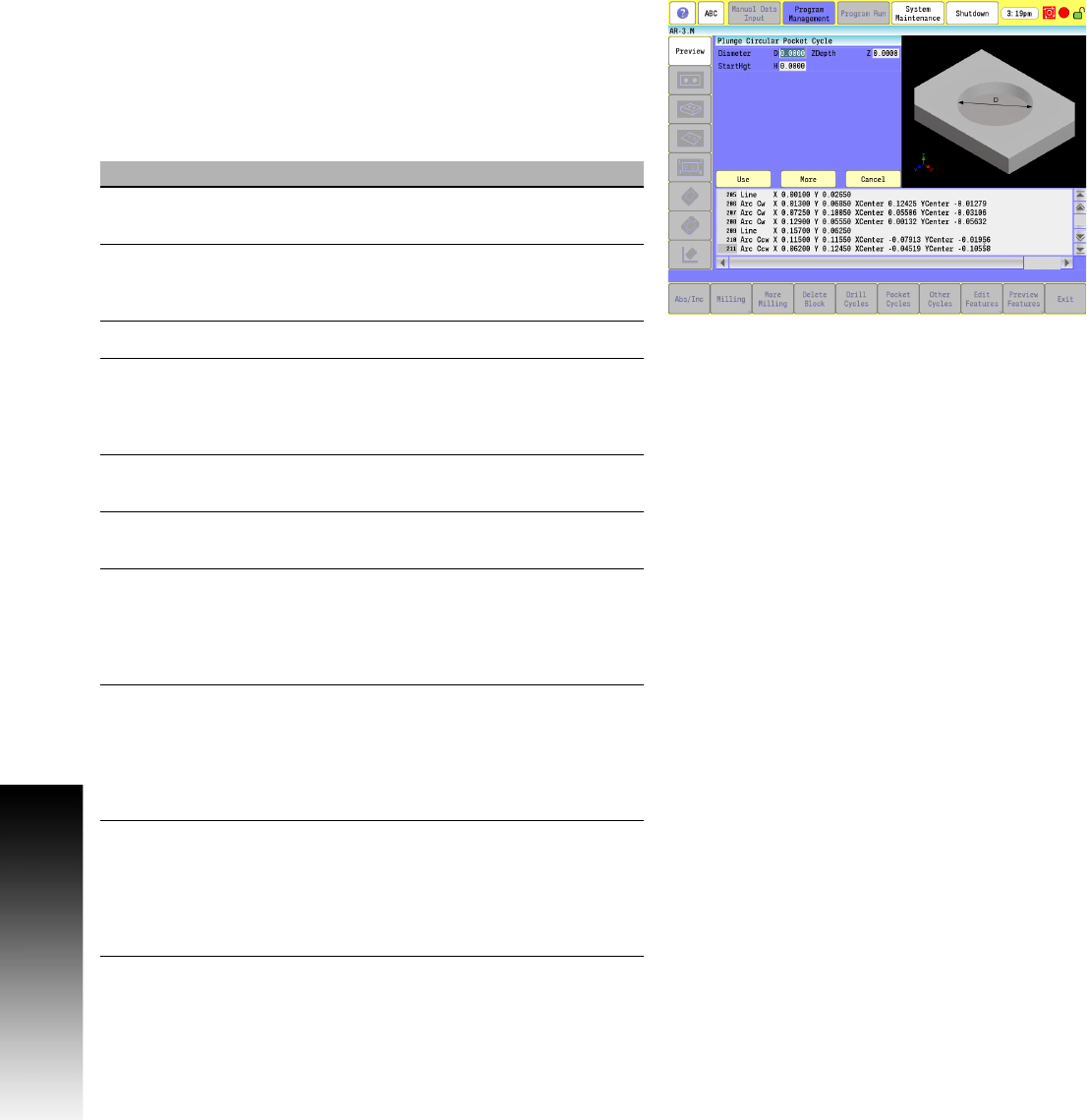
Plunge Circular Pocket Cycle
Use the plunge circular pocket cycle for carbide tooling, when a
multiple-axis ramp-in move is not possible. The Z-axis plunges
(single axis) to programmed depths. You must position the tool
directly over the center of the pocket prior to the plunge circular
pocket cycle block, or use the X Y words.
Activate the tool prior to programming so the cutter diameter is
known.
Field Code Description
Diameter D Diameter of pocket in X and Y axes.
(Required)
StartHgt H Z absolute starting height (0.1” or 2 mm
above surface). Executed in rapid.
(Required)
ZDepth Z Absolute depth of pocket. (Required)
StepOver A The distance the tool steps over (width of
cut) in the X and Y axes as it mills out the
pocket. Defaults to tool radius, which is the
max.
XCenter X X coordinate of the pocket center point.
Defaults to current position.
YCenter Y Y coordinate of the pocket center point.
Defaults to current position.
DepthCut B The depth of each cut per pass. Defaults to
tool diameter. Max is the full ZDepth in
parameter Z, less bottom finish stock. A
negative value will cause the finish pass to
finish the side walls in steps down.
FinStock S Amount of stock left by the roughing
passes for a finish pass. This amount
applies to the sides and bottom unless R
(SideStock) is defined; then, S (FinStock)
only applies to the bottom. Default is no
stock left.
SideStock R Amount of stock left by the roughing
passes for a finish pass. This amount
applies to the sides and bottom unless R
(SideStock) is defined; then, S (FinStock)
only applies to the bottom. Default is no
stock left.