
Manual


Table Of Contents
- Controls of the 3500i
- Manual Information
- Introduction
- Machining Fundamentals
- Manual Data Input
- Tool Management
- 4.1 Tool Table
- 4.2 Tool Data
- Program Management
- Conversational Editing
- Programming: Canned Cycles, sub-programs
- 7.1 Explaining Basic Cycles
- Round/Chamfer
- Rapid
- Line
- Arc
- Dwell:
- Plane Selection
- Reference Point Return:
- Fixture Offset (Work Coordinate System Select):
- Unit (Inch/MM)
- Dimension (Abs/Inc)
- Absolute Zero Set
- Block Form
- Temporary Path Tolerance
- System Data
- FeedRate
- FeedRate (4th-Axis)
- Spindle RPM
- M - Functions
- Tool Definition and Activation
- Repeat Blocks
- 7.2 Canned Cycles
- 7.3 Probing Cycles
- 7.4 Sub-programs
- 7.1 Explaining Basic Cycles
- Drawing Programs
- Running a Program on the Machine
- CAM: Programming
- 10.1 CAM Programming
- CAM Mode
- Recommended CAM Programming Sequence
- CAM Mode Mouse Operations
- CAM Mode Screen
- Activating CAM Mode
- Creating a New Program
- Tool Path Data Input
- Quick Coordinate Entry
- Job Setup: Basic tab
- Job Setup: Advanced tab
- Comment Tab
- Block Form: Basic tab
- Comment Tab
- Drilling Cycle:
- Drilling dialogue:
- Mill Cycle
- Pocket Cycle
- Pocket Finish Cycles
- Engraving Cycle
- Program Directive
- Modifying Toolbar
- Viewing Tools
- CAM Mode buttons
- CAM Setup
- Geometry
- DXF Import Feature
- Modifying Tools
- Shapes
- Tool Table
- Tool Paths
- CAM Example 1
- CAM Example 2
- 10.1 CAM Programming
- G-Code Edit, Help, & Advanced Features
- 11.1 G-Code Program Editing
- 11.2 G-Code and M-Code Definitions
- 11.3 Edit Help
- 11.4 Advanced Programming
- SPEED
- M - Functions
- Order of Execution
- Programming Non-modal Exact Stop:
- In-Position Mode (Exact Stop Check):
- Contouring Mode (Cutting Mode) :
- Setting Stroke Limit:
- Return from Reference Point:
- Move Reference from Machine Datum:
- Modifiers
- Block Separators
- Tool Offset Modification
- Expressions and Functions
- System Variables
- User Variables
- Variable Programming (Parametric Programming)
- Probe Move (G31)
- Conditional Statements
- Short Form Addressing
- Logical and Comparative Terms
- File Inclusion
- 11.5 Four Axis Programming
- Software Update
- Off-Line Software
174 7 Programming: Canned Cycles, sub-programs
7.2 Canned Cycles
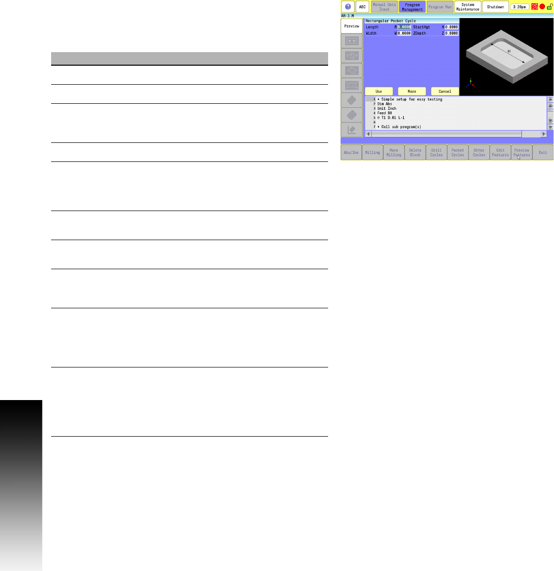
Rectangular Pocket Cycle
Use the rectangular pocket cycle to mill square or rectangular
pockets. You must position the tool directly over the center of the
pocket prior to the Rectangular Pocket cycle, or use the X Y data.
Activate a tool prior to programming, so cutter diameter is known.
Field Code Description
Length M Length of pocket in X-axis. (Required)
Width W Width of pocket in Y-axis. (Required)
StartHgt H Z absolute starting height (0.1” or 2 mm
above surface). Executed in rapid.
(Required)
ZDepth Z Absolute depth of pocket. (Required)
StepOver A The distance the tool steps over (width of
cut) in the X and Y axes as it mills out the
pocket. Defaults to tool radius, which is the
max.
XCenter X X coordinate of the pocket center point.
Defaults to current position.
YCenter Y Y coordinate of the pocket center point.
Defaults to current position.
CornerRad U The arc radius of all four corners of the
pocket. Defaults to tool radius, which is the
minimum value allowed.
DepthCut B The depth of each cut per pass. Defaults to
tool diameter. Max is the full ZDepth in
parameter Z, less bottom finish stock. A
negative value will cause the finish pass to
finish the side walls in steps down.
FinStock S Amount of stock left by the roughing
passes for a finish pass. This amount
applies to the sides and bottom unless R
(SideStock) is defined; then, S (FinStock)
only applies to the bottom. Default is no
stock left.