
Manual


Table Of Contents
- Controls of the 3500i
- Manual Information
- Introduction
- Machining Fundamentals
- Manual Data Input
- Tool Management
- 4.1 Tool Table
- 4.2 Tool Data
- Program Management
- Conversational Editing
- Programming: Canned Cycles, sub-programs
- 7.1 Explaining Basic Cycles
- Round/Chamfer
- Rapid
- Line
- Arc
- Dwell:
- Plane Selection
- Reference Point Return:
- Fixture Offset (Work Coordinate System Select):
- Unit (Inch/MM)
- Dimension (Abs/Inc)
- Absolute Zero Set
- Block Form
- Temporary Path Tolerance
- System Data
- FeedRate
- FeedRate (4th-Axis)
- Spindle RPM
- M - Functions
- Tool Definition and Activation
- Repeat Blocks
- 7.2 Canned Cycles
- 7.3 Probing Cycles
- 7.4 Sub-programs
- 7.1 Explaining Basic Cycles
- Drawing Programs
- Running a Program on the Machine
- CAM: Programming
- 10.1 CAM Programming
- CAM Mode
- Recommended CAM Programming Sequence
- CAM Mode Mouse Operations
- CAM Mode Screen
- Activating CAM Mode
- Creating a New Program
- Tool Path Data Input
- Quick Coordinate Entry
- Job Setup: Basic tab
- Job Setup: Advanced tab
- Comment Tab
- Block Form: Basic tab
- Comment Tab
- Drilling Cycle:
- Drilling dialogue:
- Mill Cycle
- Pocket Cycle
- Pocket Finish Cycles
- Engraving Cycle
- Program Directive
- Modifying Toolbar
- Viewing Tools
- CAM Mode buttons
- CAM Setup
- Geometry
- DXF Import Feature
- Modifying Tools
- Shapes
- Tool Table
- Tool Paths
- CAM Example 1
- CAM Example 2
- 10.1 CAM Programming
- G-Code Edit, Help, & Advanced Features
- 11.1 G-Code Program Editing
- 11.2 G-Code and M-Code Definitions
- 11.3 Edit Help
- 11.4 Advanced Programming
- SPEED
- M - Functions
- Order of Execution
- Programming Non-modal Exact Stop:
- In-Position Mode (Exact Stop Check):
- Contouring Mode (Cutting Mode) :
- Setting Stroke Limit:
- Return from Reference Point:
- Move Reference from Machine Datum:
- Modifiers
- Block Separators
- Tool Offset Modification
- Expressions and Functions
- System Variables
- User Variables
- Variable Programming (Parametric Programming)
- Probe Move (G31)
- Conditional Statements
- Short Form Addressing
- Logical and Comparative Terms
- File Inclusion
- 11.5 Four Axis Programming
- Software Update
- Off-Line Software
ACU-RITE 3500i 173
7. 2 C a n n e d C y c l e s
Continued:
G-code format: G73
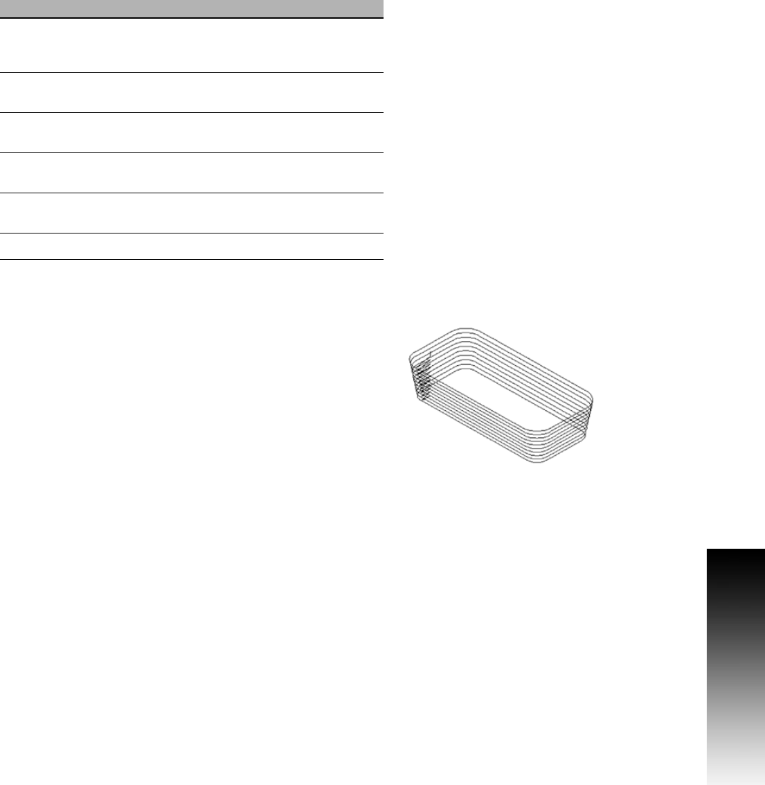
Draft Angle Pocket Example:
This program cuts the draft angle pocket shown in the figure. The
drawing does not show the finish pass. Assume an existing
rectangular pocket (4 in. long x 2 in. wide x 1 in. deep) with a
theoretical sharp lower-left corner at X2 Y2. The following program
machines a draft angle onto the existing pocket.
The tool performs the following operations:
Position the tool above the center of the lower-left corner radius.
The tool path starts and ends at the center of the lower-left corner
radius (after each perimeter pass) for all roughing passes. During
finish passes, the tool steps down the draft angle and makes passes
around the perimeter.
If a ball-end mill is programmed (W), the following points must be
considered: the length (X) and width (Y) at the bottom of the pocket
is measured at the tangency point of the ball radius, and the draft
angle. The start height (H) must be set to (0.1 + ball radius) above
surface to be cut. Set the tool-length offset so that the ball is buried
up to its centerline when at the part surface (touch off the tip and
add the ball radius, or touch off tip and use a negative length wear
equal to the ball radius).
Field Code Description
Max XY
Step
V Maximum XY tool stepover. Used if angle is
so great that the amount of XY step per Z
step exceeds 70 % of the tool diameter.
Z Step
Finish
Q Z-axis finishing step-down.
Finish STK
XY
S XY finish stock amount, sides only.
Finish
Feed
K Finish-pass feedrate.
Rough
Feed
J Roughing feedrate.
Tool Type W Flat or Ball end mill.