
Manual


Table Of Contents
- Controls of the 3500i
- Manual Information
- Introduction
- Machining Fundamentals
- Manual Data Input
- Tool Management
- 4.1 Tool Table
- 4.2 Tool Data
- Program Management
- Conversational Editing
- Programming: Canned Cycles, sub-programs
- 7.1 Explaining Basic Cycles
- Round/Chamfer
- Rapid
- Line
- Arc
- Dwell:
- Plane Selection
- Reference Point Return:
- Fixture Offset (Work Coordinate System Select):
- Unit (Inch/MM)
- Dimension (Abs/Inc)
- Absolute Zero Set
- Block Form
- Temporary Path Tolerance
- System Data
- FeedRate
- FeedRate (4th-Axis)
- Spindle RPM
- M - Functions
- Tool Definition and Activation
- Repeat Blocks
- 7.2 Canned Cycles
- 7.3 Probing Cycles
- 7.4 Sub-programs
- 7.1 Explaining Basic Cycles
- Drawing Programs
- Running a Program on the Machine
- CAM: Programming
- 10.1 CAM Programming
- CAM Mode
- Recommended CAM Programming Sequence
- CAM Mode Mouse Operations
- CAM Mode Screen
- Activating CAM Mode
- Creating a New Program
- Tool Path Data Input
- Quick Coordinate Entry
- Job Setup: Basic tab
- Job Setup: Advanced tab
- Comment Tab
- Block Form: Basic tab
- Comment Tab
- Drilling Cycle:
- Drilling dialogue:
- Mill Cycle
- Pocket Cycle
- Pocket Finish Cycles
- Engraving Cycle
- Program Directive
- Modifying Toolbar
- Viewing Tools
- CAM Mode buttons
- CAM Setup
- Geometry
- DXF Import Feature
- Modifying Tools
- Shapes
- Tool Table
- Tool Paths
- CAM Example 1
- CAM Example 2
- 10.1 CAM Programming
- G-Code Edit, Help, & Advanced Features
- 11.1 G-Code Program Editing
- 11.2 G-Code and M-Code Definitions
- 11.3 Edit Help
- 11.4 Advanced Programming
- SPEED
- M - Functions
- Order of Execution
- Programming Non-modal Exact Stop:
- In-Position Mode (Exact Stop Check):
- Contouring Mode (Cutting Mode) :
- Setting Stroke Limit:
- Return from Reference Point:
- Move Reference from Machine Datum:
- Modifiers
- Block Separators
- Tool Offset Modification
- Expressions and Functions
- System Variables
- User Variables
- Variable Programming (Parametric Programming)
- Probe Move (G31)
- Conditional Statements
- Short Form Addressing
- Logical and Comparative Terms
- File Inclusion
- 11.5 Four Axis Programming
- Software Update
- Off-Line Software
164 7 Programming: Canned Cycles, sub-programs
7.2 Canned Cycles
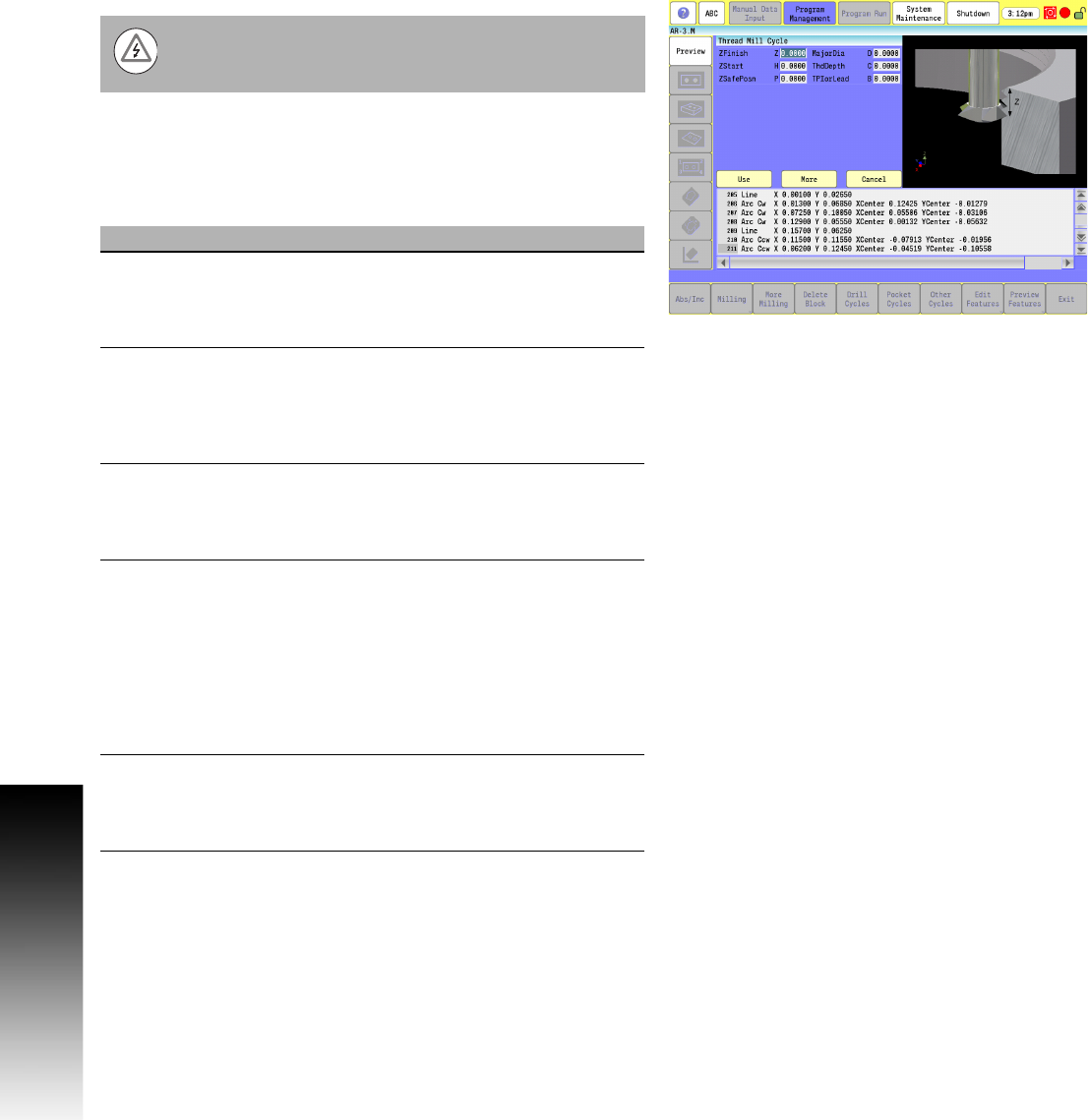
Thread Mill Cycle
Use the thread milling for cutting inside or outside threads. It cuts
either Inch or MM, left or right hand, and Z movement up or down.
A single tooth or multi-toothed tool may be used. Start can be at the
top or bottom of the hole or boss. The tools are set, as you would
normally set TLO.
The first move in this cycle is a rapid move to the center of
the thread before moving the Z axis. Make sure the tool is
properly located before calling up this cycle.
Field Code Description
ZFinish Z Absolute Z position where the thread cut
will finish. This can be above or below the
start position depending on the direction of
the thread cut: up or down. (Required)
ZStart H Absolute Z position where the thread cut
starts. This can be above or below the finish
position depending on the direction of the
thread cut, up or down. If not set, cycle
uses the current Z tool position. (Required)
ZSafePosn P An Absolute safe Z position above the part
for rapid moves in X and/or Y. (Required)
WARNING: P must be above the part to
avoid a crash while positioning.
MajorDia D Major thread Diameter. If this is a tapered
thread, it is the major diameter at the Z start
position. Hence, if you have a tapered hole
and you start at the top and cut down, you
would have a different major diameter than
if you started at the bottom and cut up. A
plus (+) value cuts in the CW direction and
a minus (-) value cuts in the CCW direction.
(Required)
ThdDepth C Depth of thread. The incremental depth of
thread on one side. A plus (+) value is inside
thread, a minus (-) value is outside thread.
(Required)