
Manual


Table Of Contents
- Controls of the 3500i
- Manual Information
- Introduction
- Machining Fundamentals
- Manual Data Input
- Tool Management
- 4.1 Tool Table
- 4.2 Tool Data
- Program Management
- Conversational Editing
- Programming: Canned Cycles, sub-programs
- 7.1 Explaining Basic Cycles
- Round/Chamfer
- Rapid
- Line
- Arc
- Dwell:
- Plane Selection
- Reference Point Return:
- Fixture Offset (Work Coordinate System Select):
- Unit (Inch/MM)
- Dimension (Abs/Inc)
- Absolute Zero Set
- Block Form
- Temporary Path Tolerance
- System Data
- FeedRate
- FeedRate (4th-Axis)
- Spindle RPM
- M - Functions
- Tool Definition and Activation
- Repeat Blocks
- 7.2 Canned Cycles
- 7.3 Probing Cycles
- 7.4 Sub-programs
- 7.1 Explaining Basic Cycles
- Drawing Programs
- Running a Program on the Machine
- CAM: Programming
- 10.1 CAM Programming
- CAM Mode
- Recommended CAM Programming Sequence
- CAM Mode Mouse Operations
- CAM Mode Screen
- Activating CAM Mode
- Creating a New Program
- Tool Path Data Input
- Quick Coordinate Entry
- Job Setup: Basic tab
- Job Setup: Advanced tab
- Comment Tab
- Block Form: Basic tab
- Comment Tab
- Drilling Cycle:
- Drilling dialogue:
- Mill Cycle
- Pocket Cycle
- Pocket Finish Cycles
- Engraving Cycle
- Program Directive
- Modifying Toolbar
- Viewing Tools
- CAM Mode buttons
- CAM Setup
- Geometry
- DXF Import Feature
- Modifying Tools
- Shapes
- Tool Table
- Tool Paths
- CAM Example 1
- CAM Example 2
- 10.1 CAM Programming
- G-Code Edit, Help, & Advanced Features
- 11.1 G-Code Program Editing
- 11.2 G-Code and M-Code Definitions
- 11.3 Edit Help
- 11.4 Advanced Programming
- SPEED
- M - Functions
- Order of Execution
- Programming Non-modal Exact Stop:
- In-Position Mode (Exact Stop Check):
- Contouring Mode (Cutting Mode) :
- Setting Stroke Limit:
- Return from Reference Point:
- Move Reference from Machine Datum:
- Modifiers
- Block Separators
- Tool Offset Modification
- Expressions and Functions
- System Variables
- User Variables
- Variable Programming (Parametric Programming)
- Probe Move (G31)
- Conditional Statements
- Short Form Addressing
- Logical and Comparative Terms
- File Inclusion
- 11.5 Four Axis Programming
- Software Update
- Off-Line Software
ACU-RITE 3500i 161
7. 2 C a n n e d C y c l e s
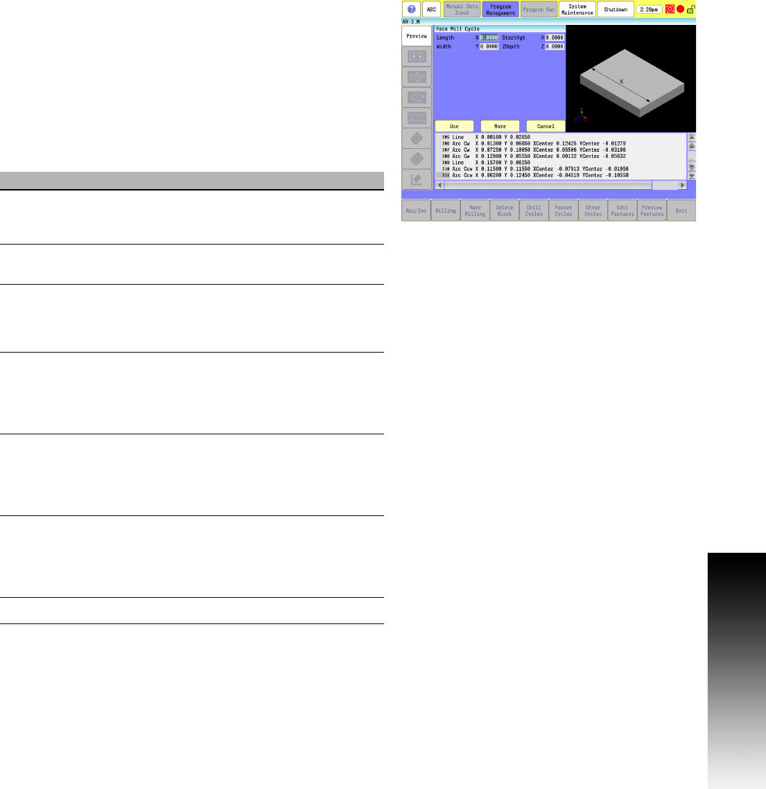
Face Mill Cycle
Facing cycles simplify the programming required to face the surface
of a part.
Execution begins one tool radius from the D and E (start point). The
selected stepover determines the approach axes.
Facing cycles can start in any corner of the surface and cut in any
direction, depending on the sign (+/-) of the X (Length) and A (Width)
values. Program a slightly oversized X and A to ensure complete
facing of the surface.
At the end of the cycle, the tool rapids to H, then rapids back to D and
E (start position).
Field Code Description
Length X The feedrate at which the tool will "ramp"
into the pocket in all three axes. Default is
last programmed feedrate.
Width Y Feedrate used during finish passes. Default
is last programmed feedrate.
StartHgt H The Absolute Z position before beginning
the facing cycle. This must be 0.1” (or 2
mm) above the surface. Executed in rapid.
(Required)
ZDepth Z Absolute depth of the finished surface.
(Required)
NOTE: ZDepth must be lower than
StartHgt. StartHgt is 0.1” (2.0 mm) above
the work surface.
XStepOver A Width of cut in the X-axis direction. When
you do not enter a value, the CNC defaults
to 70% of the active tool radius. Maximum
step-over permitted is 70% of the active
tool radius.
YStepOver B Width of cut in the Y-axis direction. When
you do not enter a value, the CNC defaults
to 70% of the active tool radius. Maximum
stepover permitted is 70% of the active tool
radius.
Feed F Feedrate used in cycle.