
Manual


Table Of Contents
- Controls of the 3500i
- Manual Information
- Introduction
- Machining Fundamentals
- Manual Data Input
- Tool Management
- 4.1 Tool Table
- 4.2 Tool Data
- Program Management
- Conversational Editing
- Programming: Canned Cycles, sub-programs
- 7.1 Explaining Basic Cycles
- Round/Chamfer
- Rapid
- Line
- Arc
- Dwell:
- Plane Selection
- Reference Point Return:
- Fixture Offset (Work Coordinate System Select):
- Unit (Inch/MM)
- Dimension (Abs/Inc)
- Absolute Zero Set
- Block Form
- Temporary Path Tolerance
- System Data
- FeedRate
- FeedRate (4th-Axis)
- Spindle RPM
- M - Functions
- Tool Definition and Activation
- Repeat Blocks
- 7.2 Canned Cycles
- 7.3 Probing Cycles
- 7.4 Sub-programs
- 7.1 Explaining Basic Cycles
- Drawing Programs
- Running a Program on the Machine
- CAM: Programming
- 10.1 CAM Programming
- CAM Mode
- Recommended CAM Programming Sequence
- CAM Mode Mouse Operations
- CAM Mode Screen
- Activating CAM Mode
- Creating a New Program
- Tool Path Data Input
- Quick Coordinate Entry
- Job Setup: Basic tab
- Job Setup: Advanced tab
- Comment Tab
- Block Form: Basic tab
- Comment Tab
- Drilling Cycle:
- Drilling dialogue:
- Mill Cycle
- Pocket Cycle
- Pocket Finish Cycles
- Engraving Cycle
- Program Directive
- Modifying Toolbar
- Viewing Tools
- CAM Mode buttons
- CAM Setup
- Geometry
- DXF Import Feature
- Modifying Tools
- Shapes
- Tool Table
- Tool Paths
- CAM Example 1
- CAM Example 2
- 10.1 CAM Programming
- G-Code Edit, Help, & Advanced Features
- 11.1 G-Code Program Editing
- 11.2 G-Code and M-Code Definitions
- 11.3 Edit Help
- 11.4 Advanced Programming
- SPEED
- M - Functions
- Order of Execution
- Programming Non-modal Exact Stop:
- In-Position Mode (Exact Stop Check):
- Contouring Mode (Cutting Mode) :
- Setting Stroke Limit:
- Return from Reference Point:
- Move Reference from Machine Datum:
- Modifiers
- Block Separators
- Tool Offset Modification
- Expressions and Functions
- System Variables
- User Variables
- Variable Programming (Parametric Programming)
- Probe Move (G31)
- Conditional Statements
- Short Form Addressing
- Logical and Comparative Terms
- File Inclusion
- 11.5 Four Axis Programming
- Software Update
- Off-Line Software
154 7 Programming: Canned Cycles, sub-programs
7.2 Canned Cycles
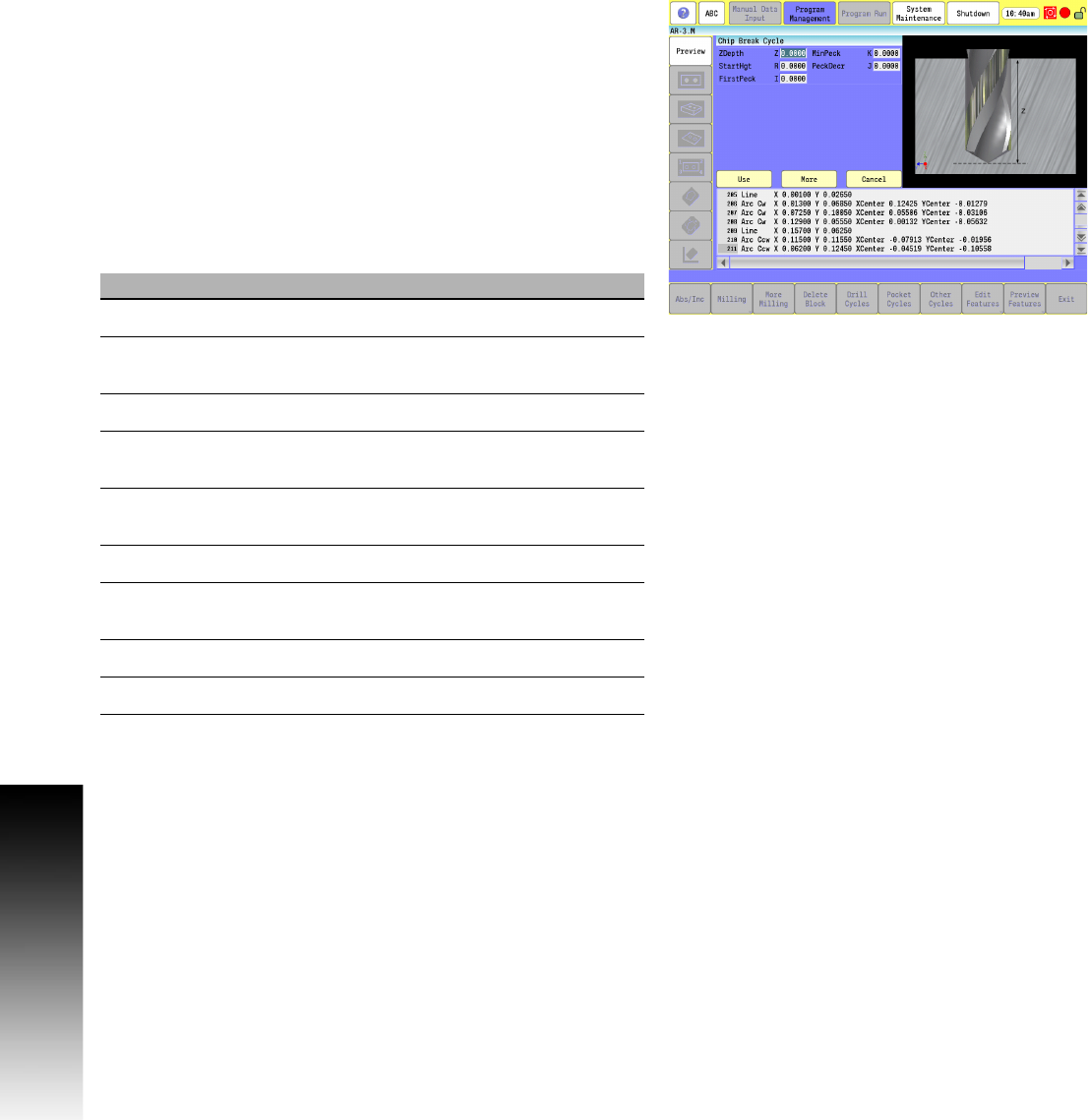
Chip Break Cycle
This is the chip-breaker peck-drilling cycle, generally used to
peck-drill medium to deep holes. The cycle feeds from the R-plane
to the first peck depth in Z, rapid retracts the chip-break increment
(W), feeds to the next calculated peck depth (initial peck less J), and
continues this sequence until it reaches a U depth, or until final hole
depth is reached. The peck distance is never more than I or less
than K.
This cycle enables optimum drilling conditions for holes. For
maximum efficiency in deep hole drilling, set parameters to
accommodate the material and tool types used. Generally, the
deeper the hole, the smaller the peck distance (J). This prevents the
binding of chips, tool, and workpiece. Set U to retract the drill
completely at set depth intervals.
G-code format: G87
Field Code Description
ZDepth Z Absolute hole depth. (Required)
MinPeck K Minimum peck distance (positive
dimension). Required.
StartHgt R Initial Z start point, in rapid. (Required)
PeckDecr J Amount to subtract from previous peck
(positive dimension). Required.
FirstPeck I First peck distance (positive dimension).
Required.
ReturnHgt P Z return point after hole depth, in rapid.
Retract
Dep
U Incremental depth between full retracts
(positive dimension).
ChipBrkInc W Chip break increment (positive dimension).
Feed F Feedrate