
Manual


Table Of Contents
- Controls of the 3500i
- Manual Information
- Introduction
- Machining Fundamentals
- Manual Data Input
- Tool Management
- 4.1 Tool Table
- 4.2 Tool Data
- Program Management
- Conversational Editing
- Programming: Canned Cycles, sub-programs
- 7.1 Explaining Basic Cycles
- Round/Chamfer
- Rapid
- Line
- Arc
- Dwell:
- Plane Selection
- Reference Point Return:
- Fixture Offset (Work Coordinate System Select):
- Unit (Inch/MM)
- Dimension (Abs/Inc)
- Absolute Zero Set
- Block Form
- Temporary Path Tolerance
- System Data
- FeedRate
- FeedRate (4th-Axis)
- Spindle RPM
- M - Functions
- Tool Definition and Activation
- Repeat Blocks
- 7.2 Canned Cycles
- 7.3 Probing Cycles
- 7.4 Sub-programs
- 7.1 Explaining Basic Cycles
- Drawing Programs
- Running a Program on the Machine
- CAM: Programming
- 10.1 CAM Programming
- CAM Mode
- Recommended CAM Programming Sequence
- CAM Mode Mouse Operations
- CAM Mode Screen
- Activating CAM Mode
- Creating a New Program
- Tool Path Data Input
- Quick Coordinate Entry
- Job Setup: Basic tab
- Job Setup: Advanced tab
- Comment Tab
- Block Form: Basic tab
- Comment Tab
- Drilling Cycle:
- Drilling dialogue:
- Mill Cycle
- Pocket Cycle
- Pocket Finish Cycles
- Engraving Cycle
- Program Directive
- Modifying Toolbar
- Viewing Tools
- CAM Mode buttons
- CAM Setup
- Geometry
- DXF Import Feature
- Modifying Tools
- Shapes
- Tool Table
- Tool Paths
- CAM Example 1
- CAM Example 2
- 10.1 CAM Programming
- G-Code Edit, Help, & Advanced Features
- 11.1 G-Code Program Editing
- 11.2 G-Code and M-Code Definitions
- 11.3 Edit Help
- 11.4 Advanced Programming
- SPEED
- M - Functions
- Order of Execution
- Programming Non-modal Exact Stop:
- In-Position Mode (Exact Stop Check):
- Contouring Mode (Cutting Mode) :
- Setting Stroke Limit:
- Return from Reference Point:
- Move Reference from Machine Datum:
- Modifiers
- Block Separators
- Tool Offset Modification
- Expressions and Functions
- System Variables
- User Variables
- Variable Programming (Parametric Programming)
- Probe Move (G31)
- Conditional Statements
- Short Form Addressing
- Logical and Comparative Terms
- File Inclusion
- 11.5 Four Axis Programming
- Software Update
- Off-Line Software
ACU-RITE 3500i 153
7. 2 C a n n e d C y c l e s
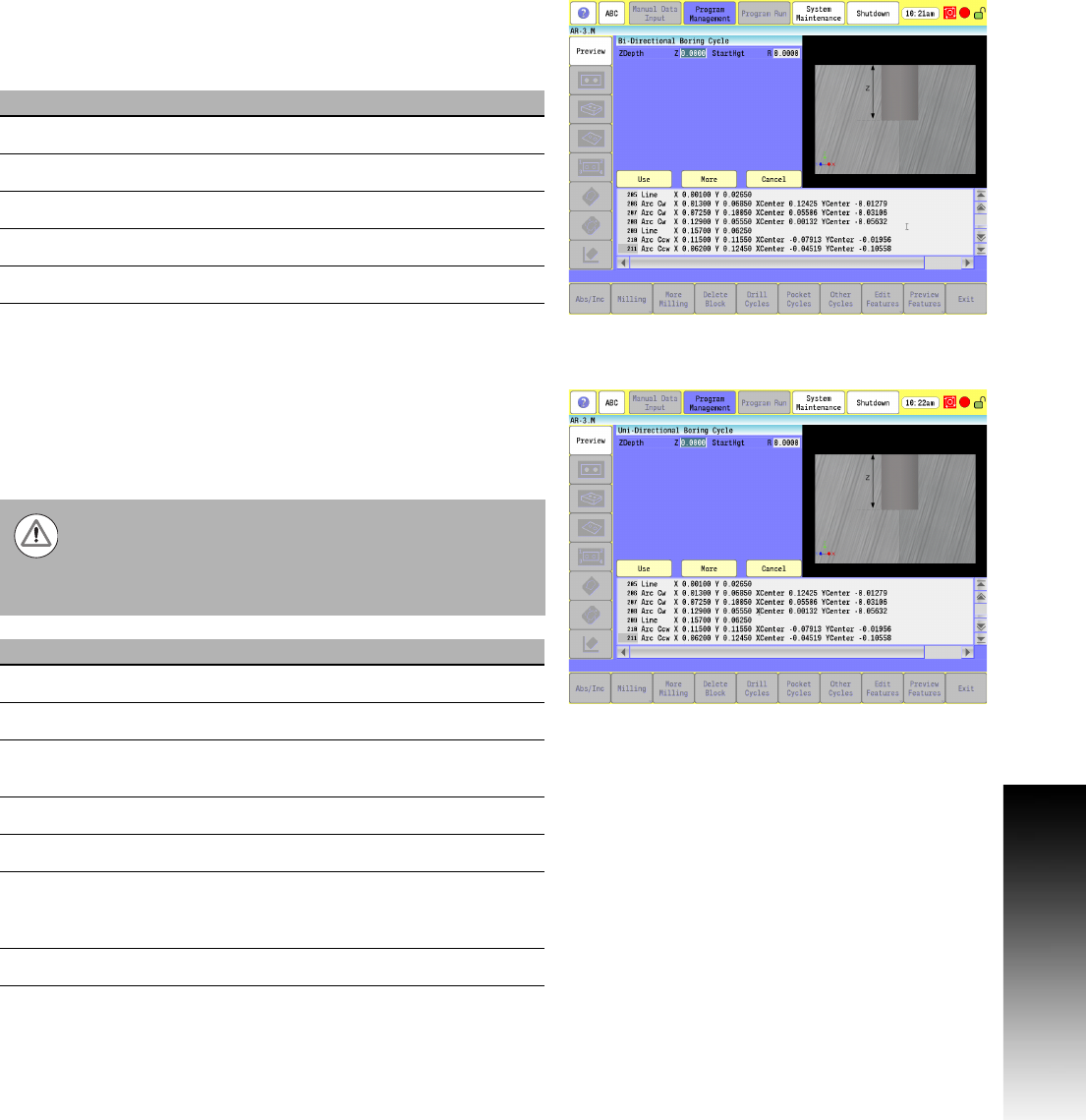
Boring Bidirectional Cycle
Boring Bidirectional is a boring cycle, generally used to make a pass
in each direction on a bore or to tap with a self-reversing tapping
head. It feeds from the R-plane to Z depth, and then feeds back to
the retract height.
G-code format: G85
Boring Unidirectional Cycle
Boring Unidirectional is a boring cycle that allows the X-axis to back
off the bore surface after the spindle has stopped and oriented itself.
The cycle feeds from the R-plane to Z depth, dwell for the specified
time, stop and orient the spindle to the specified angle C, back off
in X, rapid retract in Z, re-position in X, and restart the spindle.
G-code format: G86
Field Code Description
ZDepth Z Absolute hole depth. (Required)
StartHgt R Initial Z start point, in rapid. (Required)
ReturnHgt P Z return point after hole depth, in rapid.
Feed F Feedrate
Dwell D Dwell time
Your machine must be equipped with spindle M-functions
(Spindle Forward [M3], Spindle Reverse [M4], Spindle Off
[M5]) and spindle orientation (M19) to use this cycle. Do
not use this cycle if the machine does not have the spindle
commands and spindle orientation.
Field Code Description
ZDepth Z Absolute hole depth. (Required)
StartHgt R Initial Z start point, in rapid. (Required)
X Backoff I X-axis incremental backoff distance in X
(positive or negative dimension).
Feed F Feedrate
ReturnHgt P Z retract height after hole depth, in rapid.
Index
Angle
C M19 index angle. If no angle is given, the
angle for spindle orientation defaults to
zero.
Dwell D Dwell time (in seconds).