
Manual


Table Of Contents
- Controls of the 3500i
- Manual Information
- Introduction
- Machining Fundamentals
- Manual Data Input
- Tool Management
- 4.1 Tool Table
- 4.2 Tool Data
- Program Management
- Conversational Editing
- Programming: Canned Cycles, sub-programs
- 7.1 Explaining Basic Cycles
- Round/Chamfer
- Rapid
- Line
- Arc
- Dwell:
- Plane Selection
- Reference Point Return:
- Fixture Offset (Work Coordinate System Select):
- Unit (Inch/MM)
- Dimension (Abs/Inc)
- Absolute Zero Set
- Block Form
- Temporary Path Tolerance
- System Data
- FeedRate
- FeedRate (4th-Axis)
- Spindle RPM
- M - Functions
- Tool Definition and Activation
- Repeat Blocks
- 7.2 Canned Cycles
- 7.3 Probing Cycles
- 7.4 Sub-programs
- 7.1 Explaining Basic Cycles
- Drawing Programs
- Running a Program on the Machine
- CAM: Programming
- 10.1 CAM Programming
- CAM Mode
- Recommended CAM Programming Sequence
- CAM Mode Mouse Operations
- CAM Mode Screen
- Activating CAM Mode
- Creating a New Program
- Tool Path Data Input
- Quick Coordinate Entry
- Job Setup: Basic tab
- Job Setup: Advanced tab
- Comment Tab
- Block Form: Basic tab
- Comment Tab
- Drilling Cycle:
- Drilling dialogue:
- Mill Cycle
- Pocket Cycle
- Pocket Finish Cycles
- Engraving Cycle
- Program Directive
- Modifying Toolbar
- Viewing Tools
- CAM Mode buttons
- CAM Setup
- Geometry
- DXF Import Feature
- Modifying Tools
- Shapes
- Tool Table
- Tool Paths
- CAM Example 1
- CAM Example 2
- 10.1 CAM Programming
- G-Code Edit, Help, & Advanced Features
- 11.1 G-Code Program Editing
- 11.2 G-Code and M-Code Definitions
- 11.3 Edit Help
- 11.4 Advanced Programming
- SPEED
- M - Functions
- Order of Execution
- Programming Non-modal Exact Stop:
- In-Position Mode (Exact Stop Check):
- Contouring Mode (Cutting Mode) :
- Setting Stroke Limit:
- Return from Reference Point:
- Move Reference from Machine Datum:
- Modifiers
- Block Separators
- Tool Offset Modification
- Expressions and Functions
- System Variables
- User Variables
- Variable Programming (Parametric Programming)
- Probe Move (G31)
- Conditional Statements
- Short Form Addressing
- Logical and Comparative Terms
- File Inclusion
- 11.5 Four Axis Programming
- Software Update
- Off-Line Software
152 7 Programming: Canned Cycles, sub-programs
7.2 Canned Cycles
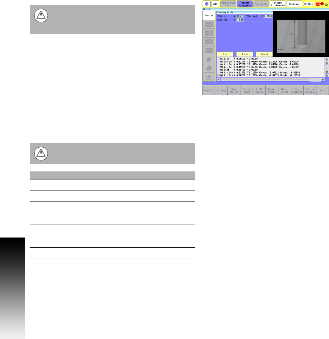
Tapping Cycle
The tapping canned cycle is used for tapping holes. During a tapping
cycle, the tool feeds from the R-plane to Z depth. The spindle stops
and reverses, the tool feeds to the retract plane, and the spindle
stops, and then reverses again.
F (TPIorLead): Enter Threads per Inch when in Inch mode. Enter
Lead when in MM mode. Lead is the distance from one thread to
the next. You must program a spindle RPM. The Feedrate is
calculated based on the spindle RPM and the TPI or Lead specified.
S (Spindle sync): To enable Spindle sync, enter a value of 1. The
machine must have direct spindle control to use this feature. The
spindle rotation and Z-axis movement is synched together, as in a
threading cycle.
D (Dwell): A dwell time value in seconds can be entered. You may
require this feature because of the time required to stop and reverse
the spindle.
G-code format: G84
The machine must be equipped with spindle M-functions
(FWD, REV, OFF) to use this cycle. Do not use the tapping
cycle if the machine does not have spindle commands
available.
The Dwell occurs before the top entry to the hole, and
before the spindle reversal at the bottom of the hole.
Field Code Description
ZDepth Z Absolute hole depth. (Required)
StartHgt R Initial Z start point, in rapid. (Required)
ReturnHgt P Z retract height after hole depth, in rapid.
Dwell D Dwell time
TPIorLead F Threads per Inch (TPI) in Inch mode or Lead
(Distance between threads) in MM mode.
(Required)
SyncSpin S Synchronized Spindle, No (0) or Yes (1).