
Manual


Table Of Contents
- Controls of the 3500i
- Manual Information
- Introduction
- Machining Fundamentals
- Manual Data Input
- Tool Management
- 4.1 Tool Table
- 4.2 Tool Data
- Program Management
- Conversational Editing
- Programming: Canned Cycles, sub-programs
- 7.1 Explaining Basic Cycles
- Round/Chamfer
- Rapid
- Line
- Arc
- Dwell:
- Plane Selection
- Reference Point Return:
- Fixture Offset (Work Coordinate System Select):
- Unit (Inch/MM)
- Dimension (Abs/Inc)
- Absolute Zero Set
- Block Form
- Temporary Path Tolerance
- System Data
- FeedRate
- FeedRate (4th-Axis)
- Spindle RPM
- M - Functions
- Tool Definition and Activation
- Repeat Blocks
- 7.2 Canned Cycles
- 7.3 Probing Cycles
- 7.4 Sub-programs
- 7.1 Explaining Basic Cycles
- Drawing Programs
- Running a Program on the Machine
- CAM: Programming
- 10.1 CAM Programming
- CAM Mode
- Recommended CAM Programming Sequence
- CAM Mode Mouse Operations
- CAM Mode Screen
- Activating CAM Mode
- Creating a New Program
- Tool Path Data Input
- Quick Coordinate Entry
- Job Setup: Basic tab
- Job Setup: Advanced tab
- Comment Tab
- Block Form: Basic tab
- Comment Tab
- Drilling Cycle:
- Drilling dialogue:
- Mill Cycle
- Pocket Cycle
- Pocket Finish Cycles
- Engraving Cycle
- Program Directive
- Modifying Toolbar
- Viewing Tools
- CAM Mode buttons
- CAM Setup
- Geometry
- DXF Import Feature
- Modifying Tools
- Shapes
- Tool Table
- Tool Paths
- CAM Example 1
- CAM Example 2
- 10.1 CAM Programming
- G-Code Edit, Help, & Advanced Features
- 11.1 G-Code Program Editing
- 11.2 G-Code and M-Code Definitions
- 11.3 Edit Help
- 11.4 Advanced Programming
- SPEED
- M - Functions
- Order of Execution
- Programming Non-modal Exact Stop:
- In-Position Mode (Exact Stop Check):
- Contouring Mode (Cutting Mode) :
- Setting Stroke Limit:
- Return from Reference Point:
- Move Reference from Machine Datum:
- Modifiers
- Block Separators
- Tool Offset Modification
- Expressions and Functions
- System Variables
- User Variables
- Variable Programming (Parametric Programming)
- Probe Move (G31)
- Conditional Statements
- Short Form Addressing
- Logical and Comparative Terms
- File Inclusion
- 11.5 Four Axis Programming
- Software Update
- Off-Line Software
146 7 Programming: Canned Cycles, sub-programs
7.1 Explaining Basic Cycles
Tool Definition and Activation
Use the Tool command to define and/or use a tool in the program. On
a machine with a fixed bin tool changer, a Tool call will always mount
the tool, with no need for the MCode 6. On a machine with a random
bin tool changer, the MCode 6 is required in order to mount the tool.
On a random type system, a Tool call without the MCode 6 will define
the tool using the specified parameters, and pre-fetch the tool by
indexing the random bin magazine to that tool's bin, but will not mount
the tool. Refer to chapter 4 "Tool Management" on page 59 for
additional information regarding tools, tool diameter and length
offsets, tool life management, tool radius compensation, and the Tool
Table.
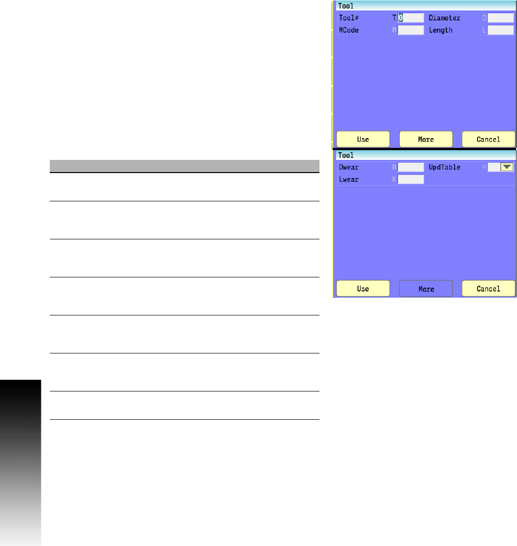
Conversational format: Tool#
G-code format: T[n]
Field Code Description
Tool# T The number of the desired miscellaneous
machine code to be activated. (Required)
MCode M The number of the desired M-Code to
activate, typically MCode 6, for mounting
the tool.
Diameter D The diameter measurement of the tool to
be used, overriding the values in the Tool
Table.
Length L The length measurement of the tool to be
used, overriding the values in the Tool
Table.
Dwear B The amount of wear to compensate for in
the diameter of the tool to be used,
overriding the values in the Tool Table.
Lwear K The amount of wear to compensate for in
the length of the tool to be used, overriding
the values in the Tool Table.
Updtable H Select Yes to permanently write/overwrite
the values specified to the Tool Table.