
Manual


Table Of Contents
- Controls of the 3500i
- Manual Information
- Introduction
- Machining Fundamentals
- Manual Data Input
- Tool Management
- 4.1 Tool Table
- 4.2 Tool Data
- Program Management
- Conversational Editing
- Programming: Canned Cycles, sub-programs
- 7.1 Explaining Basic Cycles
- Round/Chamfer
- Rapid
- Line
- Arc
- Dwell:
- Plane Selection
- Reference Point Return:
- Fixture Offset (Work Coordinate System Select):
- Unit (Inch/MM)
- Dimension (Abs/Inc)
- Absolute Zero Set
- Block Form
- Temporary Path Tolerance
- System Data
- FeedRate
- FeedRate (4th-Axis)
- Spindle RPM
- M - Functions
- Tool Definition and Activation
- Repeat Blocks
- 7.2 Canned Cycles
- 7.3 Probing Cycles
- 7.4 Sub-programs
- 7.1 Explaining Basic Cycles
- Drawing Programs
- Running a Program on the Machine
- CAM: Programming
- 10.1 CAM Programming
- CAM Mode
- Recommended CAM Programming Sequence
- CAM Mode Mouse Operations
- CAM Mode Screen
- Activating CAM Mode
- Creating a New Program
- Tool Path Data Input
- Quick Coordinate Entry
- Job Setup: Basic tab
- Job Setup: Advanced tab
- Comment Tab
- Block Form: Basic tab
- Comment Tab
- Drilling Cycle:
- Drilling dialogue:
- Mill Cycle
- Pocket Cycle
- Pocket Finish Cycles
- Engraving Cycle
- Program Directive
- Modifying Toolbar
- Viewing Tools
- CAM Mode buttons
- CAM Setup
- Geometry
- DXF Import Feature
- Modifying Tools
- Shapes
- Tool Table
- Tool Paths
- CAM Example 1
- CAM Example 2
- 10.1 CAM Programming
- G-Code Edit, Help, & Advanced Features
- 11.1 G-Code Program Editing
- 11.2 G-Code and M-Code Definitions
- 11.3 Edit Help
- 11.4 Advanced Programming
- SPEED
- M - Functions
- Order of Execution
- Programming Non-modal Exact Stop:
- In-Position Mode (Exact Stop Check):
- Contouring Mode (Cutting Mode) :
- Setting Stroke Limit:
- Return from Reference Point:
- Move Reference from Machine Datum:
- Modifiers
- Block Separators
- Tool Offset Modification
- Expressions and Functions
- System Variables
- User Variables
- Variable Programming (Parametric Programming)
- Probe Move (G31)
- Conditional Statements
- Short Form Addressing
- Logical and Comparative Terms
- File Inclusion
- 11.5 Four Axis Programming
- Software Update
- Off-Line Software
ACU-RITE 3500i 141
7.1 Explaining Basic Cycles
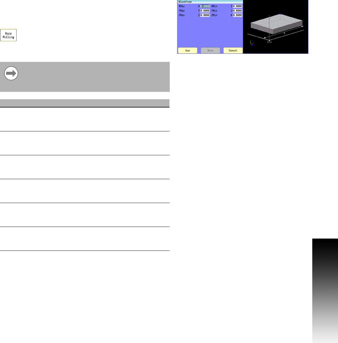
Block Form
The BlockForm command is used to define a window in relation to the
part zero. This is used by the Draw function to present a solid model
of the raw stock. Block Form can be placed anywhere within the
program and must be accompanied by all of the parameters.
Select the More Milling button, and then "BlockForm"
from the pop-up menu.
Conversational format: BlockForm
G-code format: G120
Even if there is no tool diameter compensation being
used, you must have an active tool with a diameter before
draw will graphically show material being machined from
the above stock definition.
Field Code Description
XMax X Absolute position of the most positive edge
of the part stock in the X-Axis with respect
to Absolute Zero. (Required)
YMax Y Absolute position of the most positive edge
of the part stock in the Y-Axis with respect
to Absolute Zero. (Required)
ZMax Z Absolute position of the most positive edge
of the part stock in the Z-Axis with respect
to Absolute Zero. (Required)
XMin I Absolute position of the most negative
edge of the part stock in the X-Axis with
respect to Absolute Zero. (Required)
YMin J Absolute position of the most negative
edge of the part stock in the Y-Axis with
respect to Absolute Zero. (Required)
ZMin K Absolute position of the most negative
edge of the part stock in the Z-Axis with
respect to Absolute Zero. (Required)