
Manual


Table Of Contents
- Controls of the 3500i
- Manual Information
- Introduction
- Machining Fundamentals
- Manual Data Input
- Tool Management
- 4.1 Tool Table
- 4.2 Tool Data
- Program Management
- Conversational Editing
- Programming: Canned Cycles, sub-programs
- 7.1 Explaining Basic Cycles
- Round/Chamfer
- Rapid
- Line
- Arc
- Dwell:
- Plane Selection
- Reference Point Return:
- Fixture Offset (Work Coordinate System Select):
- Unit (Inch/MM)
- Dimension (Abs/Inc)
- Absolute Zero Set
- Block Form
- Temporary Path Tolerance
- System Data
- FeedRate
- FeedRate (4th-Axis)
- Spindle RPM
- M - Functions
- Tool Definition and Activation
- Repeat Blocks
- 7.2 Canned Cycles
- 7.3 Probing Cycles
- 7.4 Sub-programs
- 7.1 Explaining Basic Cycles
- Drawing Programs
- Running a Program on the Machine
- CAM: Programming
- 10.1 CAM Programming
- CAM Mode
- Recommended CAM Programming Sequence
- CAM Mode Mouse Operations
- CAM Mode Screen
- Activating CAM Mode
- Creating a New Program
- Tool Path Data Input
- Quick Coordinate Entry
- Job Setup: Basic tab
- Job Setup: Advanced tab
- Comment Tab
- Block Form: Basic tab
- Comment Tab
- Drilling Cycle:
- Drilling dialogue:
- Mill Cycle
- Pocket Cycle
- Pocket Finish Cycles
- Engraving Cycle
- Program Directive
- Modifying Toolbar
- Viewing Tools
- CAM Mode buttons
- CAM Setup
- Geometry
- DXF Import Feature
- Modifying Tools
- Shapes
- Tool Table
- Tool Paths
- CAM Example 1
- CAM Example 2
- 10.1 CAM Programming
- G-Code Edit, Help, & Advanced Features
- 11.1 G-Code Program Editing
- 11.2 G-Code and M-Code Definitions
- 11.3 Edit Help
- 11.4 Advanced Programming
- SPEED
- M - Functions
- Order of Execution
- Programming Non-modal Exact Stop:
- In-Position Mode (Exact Stop Check):
- Contouring Mode (Cutting Mode) :
- Setting Stroke Limit:
- Return from Reference Point:
- Move Reference from Machine Datum:
- Modifiers
- Block Separators
- Tool Offset Modification
- Expressions and Functions
- System Variables
- User Variables
- Variable Programming (Parametric Programming)
- Probe Move (G31)
- Conditional Statements
- Short Form Addressing
- Logical and Comparative Terms
- File Inclusion
- 11.5 Four Axis Programming
- Software Update
- Off-Line Software
140 7 Programming: Canned Cycles, sub-programs
7.1 Explaining Basic Cycles
Absolute Zero Set
Absolute Zero is the X0, Y0, Z0 position for absolute dimensions. Refer
to chapter 3 "Manual Data Input (MDI)" on page 38 for more
information on Absolute positioning.
A SetZero block sets the Absolute Zero Reference of one or more axes
to a new position. Use SetZero in one of two ways: to reset X0 Y0 Z0
or to preset the current location to the specified coordinates.
In axis presetting, non-zero values set the current machine position to
the specified coordinates. In axis resetting, X0, Y0 and Z0 values set
the current machine position as the new Absolute Zero Reference.
In G-code programming, the equivalent G92 (Absolute Zero) cancels
Mirroring (G100), Axis Rotation (G68), and Axis Scaling (G72).
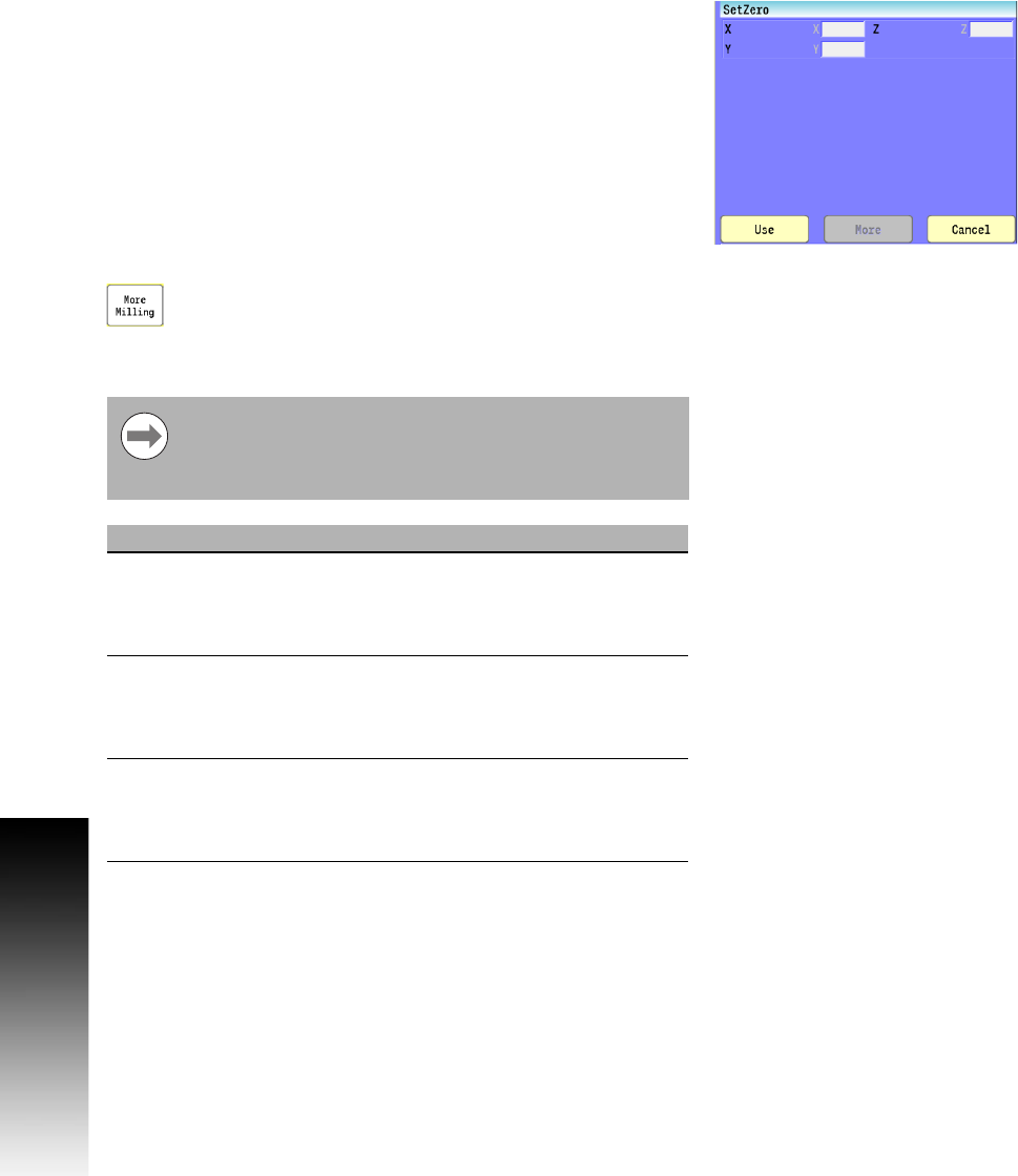
Select the More Milling button, and then "SetZero"
from the pop-up menu.
Conversational format: SetZero
G-code format: G92
It is recommended to use Fixture Offset instead of
Absolute Zero. Absolute Zero should only be used in
programs. If programmed in MDI, the Absolute Zero
cancelled when the 3500i is switched to Auto.
Field Code Description
X X The new X-Axis coordinate to assign to the
current machine position. Use a value of "0"
to define the position as the new Absolute
Zero Reference.
Y Y The new Y-Axis coordinate to assign to the
current machine position. Use a value of "0"
to define the position as the new Absolute
Zero Reference.
Z Z The new Z-Axis coordinate to assign to the
current machine position. Use a value of "0"
to define the position as the new Absolute
Zero Reference.