
Manual


Table Of Contents
- Controls of the 3500i
- Manual Information
- Introduction
- Machining Fundamentals
- Manual Data Input
- Tool Management
- 4.1 Tool Table
- 4.2 Tool Data
- Program Management
- Conversational Editing
- Programming: Canned Cycles, sub-programs
- 7.1 Explaining Basic Cycles
- Round/Chamfer
- Rapid
- Line
- Arc
- Dwell:
- Plane Selection
- Reference Point Return:
- Fixture Offset (Work Coordinate System Select):
- Unit (Inch/MM)
- Dimension (Abs/Inc)
- Absolute Zero Set
- Block Form
- Temporary Path Tolerance
- System Data
- FeedRate
- FeedRate (4th-Axis)
- Spindle RPM
- M - Functions
- Tool Definition and Activation
- Repeat Blocks
- 7.2 Canned Cycles
- 7.3 Probing Cycles
- 7.4 Sub-programs
- 7.1 Explaining Basic Cycles
- Drawing Programs
- Running a Program on the Machine
- CAM: Programming
- 10.1 CAM Programming
- CAM Mode
- Recommended CAM Programming Sequence
- CAM Mode Mouse Operations
- CAM Mode Screen
- Activating CAM Mode
- Creating a New Program
- Tool Path Data Input
- Quick Coordinate Entry
- Job Setup: Basic tab
- Job Setup: Advanced tab
- Comment Tab
- Block Form: Basic tab
- Comment Tab
- Drilling Cycle:
- Drilling dialogue:
- Mill Cycle
- Pocket Cycle
- Pocket Finish Cycles
- Engraving Cycle
- Program Directive
- Modifying Toolbar
- Viewing Tools
- CAM Mode buttons
- CAM Setup
- Geometry
- DXF Import Feature
- Modifying Tools
- Shapes
- Tool Table
- Tool Paths
- CAM Example 1
- CAM Example 2
- 10.1 CAM Programming
- G-Code Edit, Help, & Advanced Features
- 11.1 G-Code Program Editing
- 11.2 G-Code and M-Code Definitions
- 11.3 Edit Help
- 11.4 Advanced Programming
- SPEED
- M - Functions
- Order of Execution
- Programming Non-modal Exact Stop:
- In-Position Mode (Exact Stop Check):
- Contouring Mode (Cutting Mode) :
- Setting Stroke Limit:
- Return from Reference Point:
- Move Reference from Machine Datum:
- Modifiers
- Block Separators
- Tool Offset Modification
- Expressions and Functions
- System Variables
- User Variables
- Variable Programming (Parametric Programming)
- Probe Move (G31)
- Conditional Statements
- Short Form Addressing
- Logical and Comparative Terms
- File Inclusion
- 11.5 Four Axis Programming
- Software Update
- Off-Line Software
130 7 Programming: Canned Cycles, sub-programs
7.1 Explaining Basic Cycles
Arc
Arc Move:
An Arc block initiates a feed motion and is used to cut an arc in a part.
The 3500i executes arcs in the XY plane by default. For an arc in the
XZ or YZ plane, program the plane change before the arc move. After
you make all of the required moves in the XZ or YZ plane, return the
3500i to the XY plane. Refer to the section "Plane Selection" for more
information on plane selection and arc directions.
One to four axes can be included on a block with an Arc.
X, Y, Z, and U reach the target simultaneously.
Arc is modal, and remains in effect until canceled or overridden.
Arcs can be programmed in absolute or incremental, and follows the
active mode.
Specify the feedrate of the movement on or prior to the Arc block.
Conversational format: Arc CW, or Arc CCW
G-code format: G2, or G3
Press the Other button to select the Arc variant that best fits your
needs. Each variant is described next.
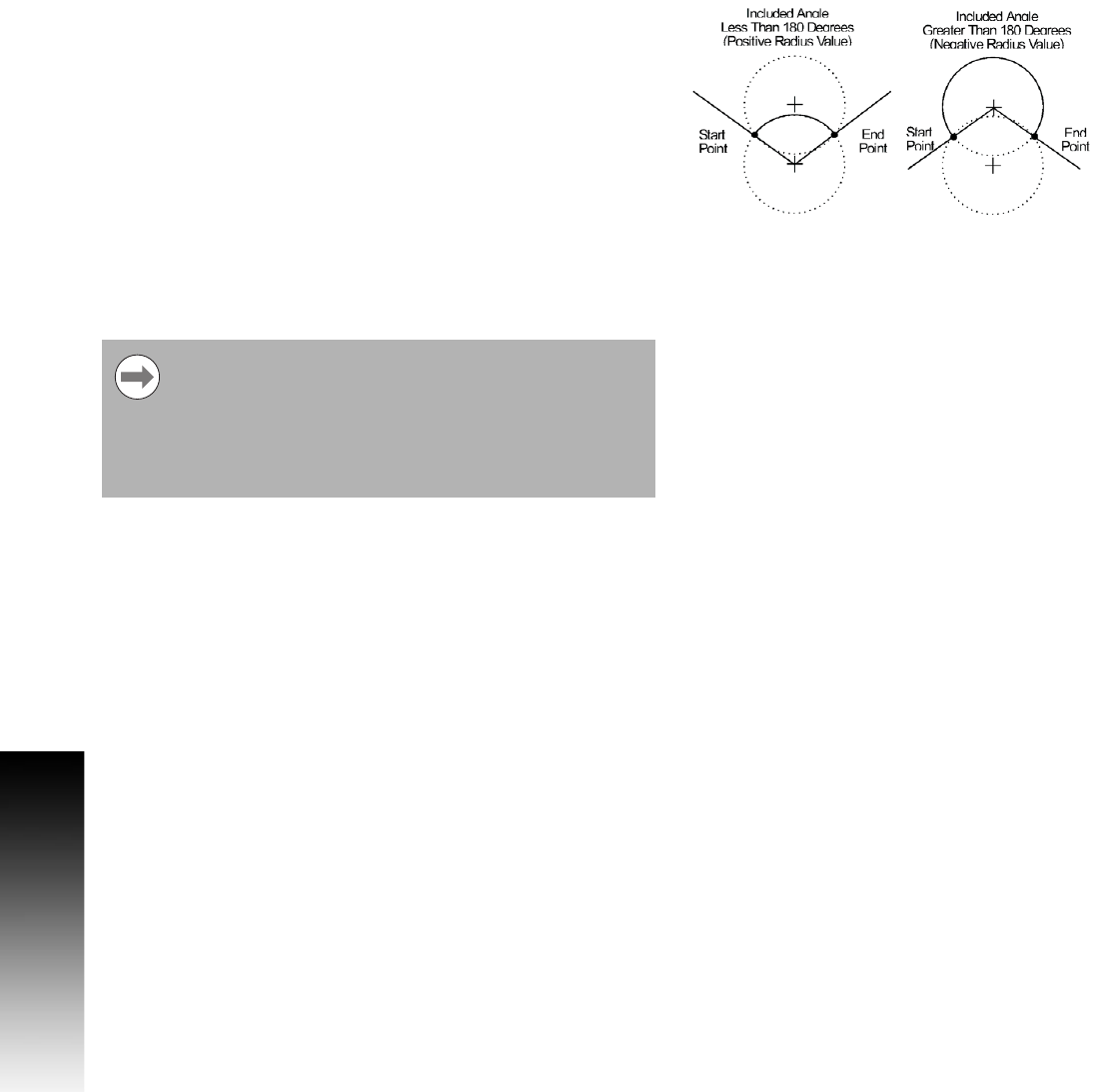
Specify the arc movement to the desired end point at the designated
radius.
Two Arcs can intersect any two points: an Arc with an included angle
less than 180 degrees and an Arc with an included angle greater than
180 degrees.
If the Arc block contains a value for the Z-Axis which
differs from the start point, a helix is generated. Helical
interpolation adds a third dimension to CW or CCW
moves. For the XY plane, the tool moves in a circular
motion in the XY axes and linearly in Z, simultaneously.
You can use helical interpolation for rough boring
applications as an example.