
Manual


Table Of Contents
- Controls of the 3500i
- Manual Information
- Introduction
- Machining Fundamentals
- Manual Data Input
- Tool Management
- 4.1 Tool Table
- 4.2 Tool Data
- Program Management
- Conversational Editing
- Programming: Canned Cycles, sub-programs
- 7.1 Explaining Basic Cycles
- Round/Chamfer
- Rapid
- Line
- Arc
- Dwell:
- Plane Selection
- Reference Point Return:
- Fixture Offset (Work Coordinate System Select):
- Unit (Inch/MM)
- Dimension (Abs/Inc)
- Absolute Zero Set
- Block Form
- Temporary Path Tolerance
- System Data
- FeedRate
- FeedRate (4th-Axis)
- Spindle RPM
- M - Functions
- Tool Definition and Activation
- Repeat Blocks
- 7.2 Canned Cycles
- 7.3 Probing Cycles
- 7.4 Sub-programs
- 7.1 Explaining Basic Cycles
- Drawing Programs
- Running a Program on the Machine
- CAM: Programming
- 10.1 CAM Programming
- CAM Mode
- Recommended CAM Programming Sequence
- CAM Mode Mouse Operations
- CAM Mode Screen
- Activating CAM Mode
- Creating a New Program
- Tool Path Data Input
- Quick Coordinate Entry
- Job Setup: Basic tab
- Job Setup: Advanced tab
- Comment Tab
- Block Form: Basic tab
- Comment Tab
- Drilling Cycle:
- Drilling dialogue:
- Mill Cycle
- Pocket Cycle
- Pocket Finish Cycles
- Engraving Cycle
- Program Directive
- Modifying Toolbar
- Viewing Tools
- CAM Mode buttons
- CAM Setup
- Geometry
- DXF Import Feature
- Modifying Tools
- Shapes
- Tool Table
- Tool Paths
- CAM Example 1
- CAM Example 2
- 10.1 CAM Programming
- G-Code Edit, Help, & Advanced Features
- 11.1 G-Code Program Editing
- 11.2 G-Code and M-Code Definitions
- 11.3 Edit Help
- 11.4 Advanced Programming
- SPEED
- M - Functions
- Order of Execution
- Programming Non-modal Exact Stop:
- In-Position Mode (Exact Stop Check):
- Contouring Mode (Cutting Mode) :
- Setting Stroke Limit:
- Return from Reference Point:
- Move Reference from Machine Datum:
- Modifiers
- Block Separators
- Tool Offset Modification
- Expressions and Functions
- System Variables
- User Variables
- Variable Programming (Parametric Programming)
- Probe Move (G31)
- Conditional Statements
- Short Form Addressing
- Logical and Comparative Terms
- File Inclusion
- 11.5 Four Axis Programming
- Software Update
- Off-Line Software
122 7 Programming: Canned Cycles, sub-programs
7.1 Explaining Basic Cycles
Rapid
Rapid Move
Rapid Move initiates rapid traverse. The machine builder sets the
actual rapid rate in the Setup Utility. Use Rapid Move to position the
tool prior to or after a cut. Do not use Rapid Move to cut a part.
One to four axes can be included on a block with Rapid Move.
X, Y, Z, and U reach the target simultaneously.
Rapid Move is modal, and remains in effect until canceled or
overridden.
Rapid Move can be programmed in absolute or incremental, and
follows the active mode.
Conversational format: Rapid
G-code format: G0
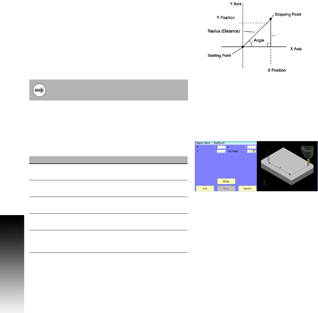
Press the Other button to select the Rapid Move variant that best fits
your needs. Each variant is described next. This figure visually depicts
the Angle and Radius parameters used in some of these variants to
specify the desired end point coordinate.
Rapid Move - EndPoint:
Specify the desired end point coordinate using actual position
designations, either in absolute or incremental.
All parameters are optional.
Rapid is overridden by the Line Move, and uses the Feed
Rate that has been provided.
Field Code Description
X X Absolute position of, or incremental
distance to, the desired X-Axis destination.
Y Y Absolute position of, or incremental
distance to, the desired Y-Axis destination.
Z Z Absolute position of, or incremental
distance to, the desired Z-Axis destination.
U U Absolute position of, or incremental
distance to, the desired U-Axis destination.
ToolComp T Select the modal tool diameter
compensation to activate or select Off to
deactivate comp.