
Manual


Table Of Contents
- Controls of the 3500i
- Manual Information
- Introduction
- Machining Fundamentals
- Manual Data Input
- Tool Management
- 4.1 Tool Table
- 4.2 Tool Data
- Program Management
- Conversational Editing
- Programming: Canned Cycles, sub-programs
- 7.1 Explaining Basic Cycles
- Round/Chamfer
- Rapid
- Line
- Arc
- Dwell:
- Plane Selection
- Reference Point Return:
- Fixture Offset (Work Coordinate System Select):
- Unit (Inch/MM)
- Dimension (Abs/Inc)
- Absolute Zero Set
- Block Form
- Temporary Path Tolerance
- System Data
- FeedRate
- FeedRate (4th-Axis)
- Spindle RPM
- M - Functions
- Tool Definition and Activation
- Repeat Blocks
- 7.2 Canned Cycles
- 7.3 Probing Cycles
- 7.4 Sub-programs
- 7.1 Explaining Basic Cycles
- Drawing Programs
- Running a Program on the Machine
- CAM: Programming
- 10.1 CAM Programming
- CAM Mode
- Recommended CAM Programming Sequence
- CAM Mode Mouse Operations
- CAM Mode Screen
- Activating CAM Mode
- Creating a New Program
- Tool Path Data Input
- Quick Coordinate Entry
- Job Setup: Basic tab
- Job Setup: Advanced tab
- Comment Tab
- Block Form: Basic tab
- Comment Tab
- Drilling Cycle:
- Drilling dialogue:
- Mill Cycle
- Pocket Cycle
- Pocket Finish Cycles
- Engraving Cycle
- Program Directive
- Modifying Toolbar
- Viewing Tools
- CAM Mode buttons
- CAM Setup
- Geometry
- DXF Import Feature
- Modifying Tools
- Shapes
- Tool Table
- Tool Paths
- CAM Example 1
- CAM Example 2
- 10.1 CAM Programming
- G-Code Edit, Help, & Advanced Features
- 11.1 G-Code Program Editing
- 11.2 G-Code and M-Code Definitions
- 11.3 Edit Help
- 11.4 Advanced Programming
- SPEED
- M - Functions
- Order of Execution
- Programming Non-modal Exact Stop:
- In-Position Mode (Exact Stop Check):
- Contouring Mode (Cutting Mode) :
- Setting Stroke Limit:
- Return from Reference Point:
- Move Reference from Machine Datum:
- Modifiers
- Block Separators
- Tool Offset Modification
- Expressions and Functions
- System Variables
- User Variables
- Variable Programming (Parametric Programming)
- Probe Move (G31)
- Conditional Statements
- Short Form Addressing
- Logical and Comparative Terms
- File Inclusion
- 11.5 Four Axis Programming
- Software Update
- Off-Line Software
ACU-RITE 3500i 117
6.1 Conversational Programming
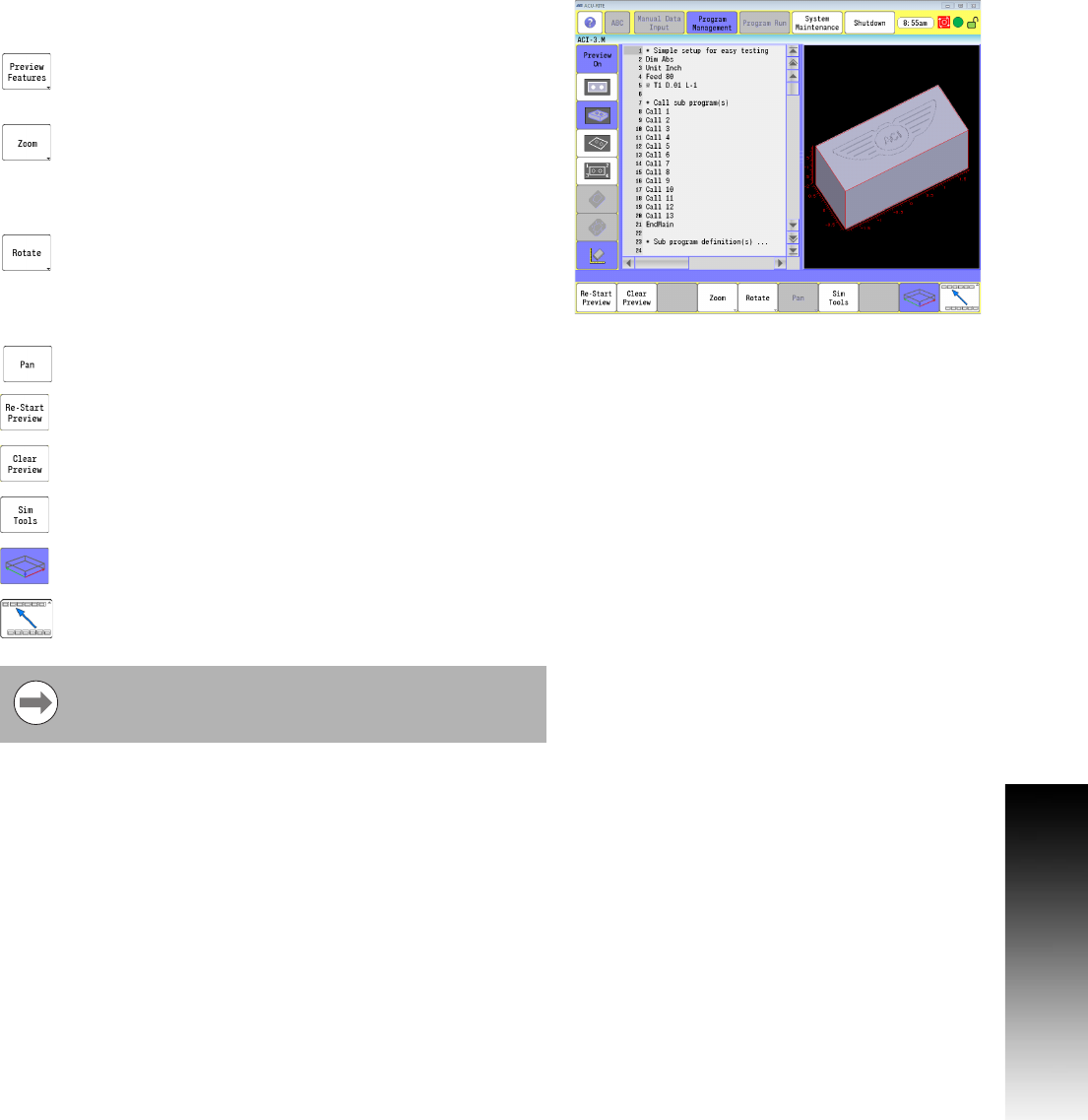
Preview Features Menu
For a complete description of the pan and rotate buttons see "Rotate
Drawing View" on page 261, also see "Pan Drawing View" on page 261.
On screen preview buttons are available in the
Preview Features menu. From the Edit screen, touch
the Preview Features button.
To zoom in or out, touch the zoom button. The Zoom In,
and Zoom Out buttons are now available. When using
a mouse to zoom in, or out in the preview window,
place the cursor over the area to be viewed, and
rotate the wheel on the mouse.
To rotate the view, touch the Rotate button. Four
directional rotate keys are now available. Each key
will incrementally rotate the view in the direction
indicated on the rotational key. The 3D model can also
be rotated by touching, and dragging.
To pan the preview, touch the Pan button. Directional
arrow buttons become available.
Re-Start Preview will re-draw the entire part graphic
.
Clear Preview will clear any part graphics but leave
the blockform in place.
Sim Tools loads the simulation tool table. Refer to
Chapter 8 "Viewing Programs" on page 256.
The Show/Hide Block Form will show or hide the block
form only when in 3D solid mode.
Returns the user to the main preview menu.
The Sim Tool and Sim Offset tables are only accessible
when the feature is enabled in the configuration. See
"Simulation Tool and Offset Tables" on page 71.