
Manual


Table Of Contents
- Controls of the 3500i
- Manual Information
- Introduction
- Machining Fundamentals
- Manual Data Input
- Tool Management
- 4.1 Tool Table
- 4.2 Tool Data
- Program Management
- Conversational Editing
- Programming: Canned Cycles, sub-programs
- 7.1 Explaining Basic Cycles
- Round/Chamfer
- Rapid
- Line
- Arc
- Dwell:
- Plane Selection
- Reference Point Return:
- Fixture Offset (Work Coordinate System Select):
- Unit (Inch/MM)
- Dimension (Abs/Inc)
- Absolute Zero Set
- Block Form
- Temporary Path Tolerance
- System Data
- FeedRate
- FeedRate (4th-Axis)
- Spindle RPM
- M - Functions
- Tool Definition and Activation
- Repeat Blocks
- 7.2 Canned Cycles
- 7.3 Probing Cycles
- 7.4 Sub-programs
- 7.1 Explaining Basic Cycles
- Drawing Programs
- Running a Program on the Machine
- CAM: Programming
- 10.1 CAM Programming
- CAM Mode
- Recommended CAM Programming Sequence
- CAM Mode Mouse Operations
- CAM Mode Screen
- Activating CAM Mode
- Creating a New Program
- Tool Path Data Input
- Quick Coordinate Entry
- Job Setup: Basic tab
- Job Setup: Advanced tab
- Comment Tab
- Block Form: Basic tab
- Comment Tab
- Drilling Cycle:
- Drilling dialogue:
- Mill Cycle
- Pocket Cycle
- Pocket Finish Cycles
- Engraving Cycle
- Program Directive
- Modifying Toolbar
- Viewing Tools
- CAM Mode buttons
- CAM Setup
- Geometry
- DXF Import Feature
- Modifying Tools
- Shapes
- Tool Table
- Tool Paths
- CAM Example 1
- CAM Example 2
- 10.1 CAM Programming
- G-Code Edit, Help, & Advanced Features
- 11.1 G-Code Program Editing
- 11.2 G-Code and M-Code Definitions
- 11.3 Edit Help
- 11.4 Advanced Programming
- SPEED
- M - Functions
- Order of Execution
- Programming Non-modal Exact Stop:
- In-Position Mode (Exact Stop Check):
- Contouring Mode (Cutting Mode) :
- Setting Stroke Limit:
- Return from Reference Point:
- Move Reference from Machine Datum:
- Modifiers
- Block Separators
- Tool Offset Modification
- Expressions and Functions
- System Variables
- User Variables
- Variable Programming (Parametric Programming)
- Probe Move (G31)
- Conditional Statements
- Short Form Addressing
- Logical and Comparative Terms
- File Inclusion
- 11.5 Four Axis Programming
- Software Update
- Off-Line Software
82 4 Tool Management
4.2 Tool Data
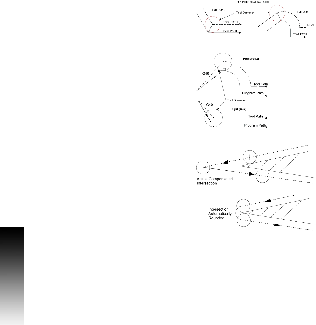
Intersecting Points
You cannot program a plane change during tool compensation.
However, a 2-axis move off the currently active plane is allowed.
For example: The active plane (compensation in XY). You program an
XZ or YZ move. The Z-axis reaches the programmed target as X/Y
reaches its compensated target. Helical moves in the active plane are
also allowed.
Program cancel compensation (G40) alone or with a move in the active
plane. The move must be in rapid or feedrate. The move must be at
least the tool radius in length.
The CNC “looks ahead” to following blocks in order to compensate
correctly. When it “sees” an upcoming cancel compensation block,
the CNC positions the tool perpendicular to the last move before the
block.
The tool moves to a point perpendicular to the last move before the
deactivation move.
Compensation Around Acute Angles
During compensation, the CNC finds the compensated intersection of
moves and travels to that point.
On very sharp angles, this is not always desirable. For example, if you
compensate along the outside of a 15-degree corner angle, the
compensated intersection point is far away from the actual point on
the work. Time is wasted by “cutting air” until the compensated point
is reached. To save time, the CNC creates an arc around the end of the
point on the work.
The CNC applies the arc where there are angles of 15 degrees or less.
This can be set in the Setup Utility or in the program. To change the
angle via program, set #1031.
Example: to change an angle to 10 degrees, program: #1031=10.
Re-program this value to 15 degrees (default) when finished.
The CNC will automatically “round” the compensated intersection.
The work remains a sharp corner.