
Manual


Table Of Contents
- Controls of the 3500i
- Manual Information
- Introduction
- Machining Fundamentals
- Manual Data Input
- Tool Management
- 4.1 Tool Table
- 4.2 Tool Data
- Program Management
- Conversational Editing
- Programming: Canned Cycles, sub-programs
- 7.1 Explaining Basic Cycles
- Round/Chamfer
- Rapid
- Line
- Arc
- Dwell:
- Plane Selection
- Reference Point Return:
- Fixture Offset (Work Coordinate System Select):
- Unit (Inch/MM)
- Dimension (Abs/Inc)
- Absolute Zero Set
- Block Form
- Temporary Path Tolerance
- System Data
- FeedRate
- FeedRate (4th-Axis)
- Spindle RPM
- M - Functions
- Tool Definition and Activation
- Repeat Blocks
- 7.2 Canned Cycles
- 7.3 Probing Cycles
- 7.4 Sub-programs
- 7.1 Explaining Basic Cycles
- Drawing Programs
- Running a Program on the Machine
- CAM: Programming
- 10.1 CAM Programming
- CAM Mode
- Recommended CAM Programming Sequence
- CAM Mode Mouse Operations
- CAM Mode Screen
- Activating CAM Mode
- Creating a New Program
- Tool Path Data Input
- Quick Coordinate Entry
- Job Setup: Basic tab
- Job Setup: Advanced tab
- Comment Tab
- Block Form: Basic tab
- Comment Tab
- Drilling Cycle:
- Drilling dialogue:
- Mill Cycle
- Pocket Cycle
- Pocket Finish Cycles
- Engraving Cycle
- Program Directive
- Modifying Toolbar
- Viewing Tools
- CAM Mode buttons
- CAM Setup
- Geometry
- DXF Import Feature
- Modifying Tools
- Shapes
- Tool Table
- Tool Paths
- CAM Example 1
- CAM Example 2
- 10.1 CAM Programming
- G-Code Edit, Help, & Advanced Features
- 11.1 G-Code Program Editing
- 11.2 G-Code and M-Code Definitions
- 11.3 Edit Help
- 11.4 Advanced Programming
- SPEED
- M - Functions
- Order of Execution
- Programming Non-modal Exact Stop:
- In-Position Mode (Exact Stop Check):
- Contouring Mode (Cutting Mode) :
- Setting Stroke Limit:
- Return from Reference Point:
- Move Reference from Machine Datum:
- Modifiers
- Block Separators
- Tool Offset Modification
- Expressions and Functions
- System Variables
- User Variables
- Variable Programming (Parametric Programming)
- Probe Move (G31)
- Conditional Statements
- Short Form Addressing
- Logical and Comparative Terms
- File Inclusion
- 11.5 Four Axis Programming
- Software Update
- Off-Line Software
ACU-RITE 3500i 81
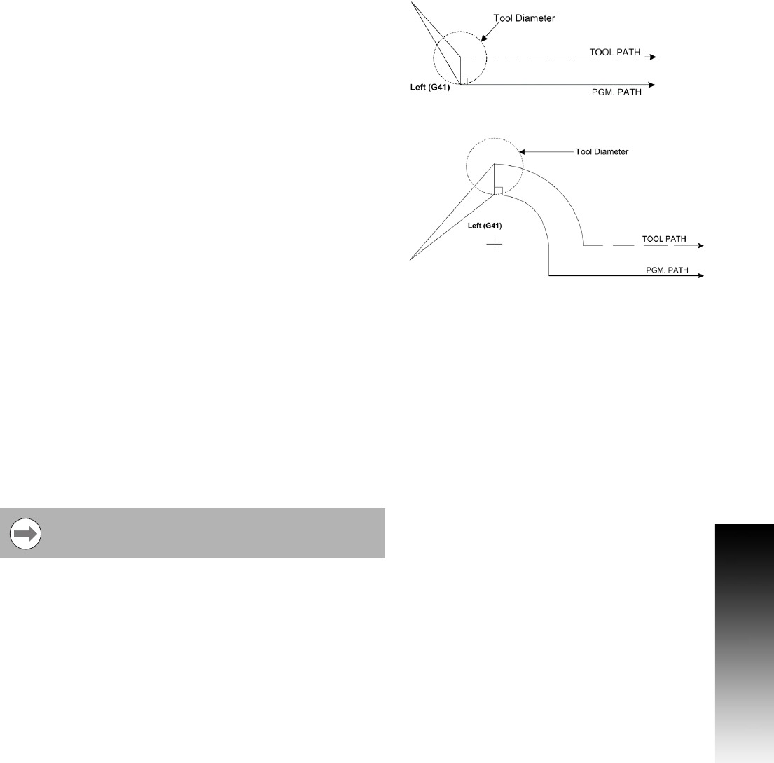
4.2 Tool Data
Tool Compensation Path
Path of Tool During Tool Compensation
In linear-to-linear or linear-to-circular moves, the position at the end of
the startup block Compensation LEFT (G41), or Compensation RIGHT
(G42), is perpendicular to the next programmed move in the plane.
In either case, the axes moves to a point perpendicular to the next
move during the startup block.
The length of the XY move that activates compensation must be equal
to or greater than the tool radius value. Example: If tool radius equals
0.3750", the vector length of the XY move that activates compensation
must be 0.3750" or greater.
The same applies to Compensation OFF move (G40).
During tool compensation, the CNC performs offset correctly and
automatically. Non-positioning moves such as dwells (except dwell
zero or infinite dwells), coolant, or other auxiliary functions are allowed
(except Optional Program Stop, and Program Stop Mode, these are
not allowed). Moves in the third axis are also allowed during
compensation.
It is recommended to use the previously described Entry
and Exit moves.