
Manual


Table Of Contents
- Controls of the 3500i
- Manual Information
- Introduction
- Machining Fundamentals
- Manual Data Input
- Tool Management
- 4.1 Tool Table
- 4.2 Tool Data
- Program Management
- Conversational Editing
- Programming: Canned Cycles, sub-programs
- 7.1 Explaining Basic Cycles
- Round/Chamfer
- Rapid
- Line
- Arc
- Dwell:
- Plane Selection
- Reference Point Return:
- Fixture Offset (Work Coordinate System Select):
- Unit (Inch/MM)
- Dimension (Abs/Inc)
- Absolute Zero Set
- Block Form
- Temporary Path Tolerance
- System Data
- FeedRate
- FeedRate (4th-Axis)
- Spindle RPM
- M - Functions
- Tool Definition and Activation
- Repeat Blocks
- 7.2 Canned Cycles
- 7.3 Probing Cycles
- 7.4 Sub-programs
- 7.1 Explaining Basic Cycles
- Drawing Programs
- Running a Program on the Machine
- CAM: Programming
- 10.1 CAM Programming
- CAM Mode
- Recommended CAM Programming Sequence
- CAM Mode Mouse Operations
- CAM Mode Screen
- Activating CAM Mode
- Creating a New Program
- Tool Path Data Input
- Quick Coordinate Entry
- Job Setup: Basic tab
- Job Setup: Advanced tab
- Comment Tab
- Block Form: Basic tab
- Comment Tab
- Drilling Cycle:
- Drilling dialogue:
- Mill Cycle
- Pocket Cycle
- Pocket Finish Cycles
- Engraving Cycle
- Program Directive
- Modifying Toolbar
- Viewing Tools
- CAM Mode buttons
- CAM Setup
- Geometry
- DXF Import Feature
- Modifying Tools
- Shapes
- Tool Table
- Tool Paths
- CAM Example 1
- CAM Example 2
- 10.1 CAM Programming
- G-Code Edit, Help, & Advanced Features
- 11.1 G-Code Program Editing
- 11.2 G-Code and M-Code Definitions
- 11.3 Edit Help
- 11.4 Advanced Programming
- SPEED
- M - Functions
- Order of Execution
- Programming Non-modal Exact Stop:
- In-Position Mode (Exact Stop Check):
- Contouring Mode (Cutting Mode) :
- Setting Stroke Limit:
- Return from Reference Point:
- Move Reference from Machine Datum:
- Modifiers
- Block Separators
- Tool Offset Modification
- Expressions and Functions
- System Variables
- User Variables
- Variable Programming (Parametric Programming)
- Probe Move (G31)
- Conditional Statements
- Short Form Addressing
- Logical and Comparative Terms
- File Inclusion
- 11.5 Four Axis Programming
- Software Update
- Off-Line Software
78 4 Tool Management
4.2 Tool Data
Ramping into a Compensation Move
Entry moves allow a smooth transition into a contour. Allowing a
way to avoid areas you do not want to affect with the tool when
entering a contour, Entry Move button (G36). If an entry move
without compensation is required, program a tool with “0” radius.
Four types of entry moves are available. Refer to Line Tangent Entry
Move, Line Perpendicular Entry Move, Arc Tangent Entry Move and
Line Arc Tangent Entry Move.
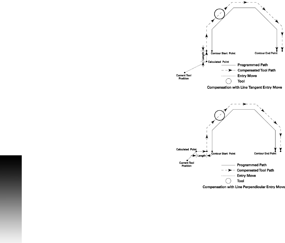
Line Tangent Entry Move
In a line tangent entry move the tool approaches the contour in a line
move tangent to the first move of the contour.
The tool feeds from the current position to a calculated point based on
the Length (L) parameter then feeds to the compensated starting
point of the contour in a line move tangent to the first move of the
contour. The direction of the entry move can be reversed by
programming a negative Length (L). All programmed Z movements
occur during the entry move (G41 Xx Yy Zz G36 Q1 Ll).
The line tangent exit move is executed the same as the entry, but in
reverse order (G37 Q1 Ll).
Line Perpendicular Entry Move
In a line perpendicular entry move the tool approaches the contour in
a line move perpendicular to the first move of the contour.
The tool feeds from the current position to a calculated point based on
the Length (L) parameter then feeds to the compensated starting
point of the contour in a line move perpendicular to the first move of
the contour. The direction of the entry move can be reversed by
programming a negative Length (L). All programmed Z movements
occur during the entry move (G41 Xx Yy Zz G36 Q2 Ll).
The line perpendicular exit move is executed the same as the entry,
but in reverse order (G37 Q2 Ll).