
Data Sheet

E
x
t
e
r
n
al
Co
n
n
e
ctio
n
s
D
e
t
a
i
l
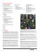
X1 PQ12 actuator connector
5 pin, 1 mm Pitch FPC connector
X6
C
ont
r
ol
i
nt
e
r
f
a
c
e
Pin Function
P1
S
p
e
e
d
Cont
r
ol
Sets maximum actuator speed
CW Faster
CCW Slower
P2 Limit Controls
Left Potentiometer controls Retract Limit
CW Maximum Stroke
Right Potentiometer controls Extend Limit
CW Maximum Stroke
P3 Sensitivity adjustment
CW Smaller dead-band
CCW Larger dead-band
1
2
3
4
5
G
r
o
u
nd
5–24 VDC Power
RC / Hobby Servo input signal
Current input signal (4–20 mA)
Voltage input signal (0–3.3 V) or 1 kHz PWM
X2
L
1
2
–
P/
L
1
6
-
P
a
ctu
a
tor
c
o
n
n
e
ctor
Pin
1
2
3
4
5
F
unc
t
ion
Potentiometer Reference Negative (yellow)
Motor Terminal (black)
Motor Terminal (red)
Potentiometer Feedback (wiper) (purple)
Potentiometer Reference Positive (orange)
X3
R
a
d
i
o
cont
r
ol
re
c
eiv
e
r conn
e
c
t
or
Pin
1
2
3
F
unc
t
ion
Ground (black)
Power (red)
Control (white)
X4
L
a
r
g
e
a
c
t
u
at
o
r conn
e
ct
o
r
P3
Pin
1
2
3
4
5
F
unc
t
ion
Potentiometer Reference Positive (whit
e)
Potentiometer Feedback (wiper) (yellow
)
Motor Terminal (red)
Motor Terminal (black)
Potentiometer Reference Negative (blue)
NOTE: If the actuator moves to one end
then stops, swap pins 3 and 4 to change
the motor direction.
X2
X3
P1
X1
X5
U
n
ive
r
s
a
l
Se
r
ia
l
B
u
s
(
M
al
e
M
i
n
i
-
B)
X6
Pin
1
2
3
4
5
F
unc
t
ion
N/C
Data
Data
N/C
Ground
X4
X5
P2
C
onn
e
c
t
or P
i
ns
nu
m
b
e
r
e
d
f
rom
Top
t
o Bo
tt
om or
L
e
f
t
t
o Right
C
ont
r
o
l
M
od
e
s
0–3.3 V Interface Mode: This mode allows an actuator to be con-
trolled with just a battery, and a potentiometer to signal the de-
sired position to the actuator – a simple interface for prototypes
or home automation projects. The desired actuator position (set-
point) is input to the CIB on connector X6 pin 5 as a voltage betw-
een ground and 3.3 V. The set-point voltage must be held on pin 5
to reach and maintain the desired actuator stroke position. The
wiper pin of an external potentiometer connects to X6 pin 5. Pins
1 and 5 of X4 can be used as the 3.3V Reference. The other two
potentiometer pins connect to these. When a Potentiometer is no
t
used, ensure the control signal ground is connected to LAC ground.
4
–
2
0 mA I
n
t
e
r
f
a
ce
M
ode
:
T
h
is
m
o
d
e
is
c
o
m
p
ati
b
le
w
i
th
P
LC
d
e
v
i
ces
typically used in industrial control applications. The desired actuator
position (set-point) is input to the LAC on connector X6 pin 4 as a
current between 4 mA and 20 mA. The set-point current must be held
on pin 4
to reach and maintain the desired actuator stroke position.
PWM Mode: This mode allows control of the actuator using a single
digital output pin from an external micro controller. The desired
actuator position is encoded as the duty cycle of a 3.3 Volt, 1 kHz
square wave on LAC connector X6 pin 5, where the percent duty cycle
sets the actuator position to the same percent of full stroke extension.
100% duty cycle represents full extension, and 0% duty cycle
represents full retraction. This input is 5V tolerent, however the % duty
cycle range will differ.
USB Mode: This mode allows control of the actuator using a Computer.
In addition advanced settings allow fine control over the controller
response. Default settings can be reverted to, using the reset command
.
When custom settings are turned on, P1, P2, and P3 are ignored. These
settings will be saved even when power is cycled. This allows custom
configuration for all inputs even when USB is not connected. Details of
the DLL are given in a separate document so that custom programs can
be created by the customer. An example Labview program is available
for download. The Dynamic Link Library(DLL) allows Programming in
many windows languages including Labview.
R
C
S
e
r
v
o
I
n
t
e
r
f
a
c
e
M
od
e
:
T
hi
s
i
s
a
sta
nd
a
r
d
h
o
bb
y
-
ty
p
e
r
e
m
o
te
-
control digital servo interface, compatible with servos and receiv-
ers from manufacturers like Futaba™ and Hi-Tec™. The desired
actuator position is input to the LAC on connector X6 pin 3 as a
positive 5 Volt pulse-width signal. A 1 ms pulse commands the
controller to fully retract the actuator, and a 2 ms pulse signals
full extension. Connector X3 can also be used for the RC control
signal, and uses the standard 3 pin 0.1" spacing typical on most
hobby servo receivers. Do not connect power to both X6 and X3
at the same time (If the supply voltages differ, large currents wi
ll
flow).
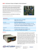
LAC • Control Board for Actuonix Linear Actuators Actuonix Motion Devices
I
n
c
.
f
o
r
m
o
re
i
n
f
o
vi
s
i
t
www
.
Actuonix
.
c
o
m