
Data Sheet

LAC
•
Actuonix
Linear
A
ct
u
ator
C
on
tr
o
l B
o
ard
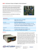
The Linear Actuator Control Board is a stand-alone closed-loop control board
specifically designed for Actuonix actuators. The LAC greatly simplifies designs by
saving the development time, cost, and processor overhead associated with
direct motor control. As little as 1 digital or analog output is required for
position control. Supported input signals include USB, Voltage, Current, RC
Servo, and PWM. Actuonix motor control IC uses a software based algorithm to
optimize position and speed control. This makes the LAC compatible with a wide
range of actuators, using only the default settings. Actuonix’s Advanced
Configuration Program allows full customization of actuator response. A stall
detection feature provides a gr eat increase in actuator life for applications that
may briefly exceed the rated force.
T
h
e
L
A
C
can
b
e
o
p
e
r
a
t
e
d
as
b
o
th an
i
n
t
e
r
f
a
c
e
b
o
a
rd
,
o
r as
a
sta
n
d
al
o
n
e
controller with the addition of an external potentiometer and power supply.
(
A
c
c
ess
o
ry
k
i
t
an
d
h
o
u
s
i
n
g
s
o
l
d
se
pa
r
a
tel
y
)
L
12
–
P
Ac
tu
a
to
rs
wit
h
p
o
s
itio
n
f
ee
db
a
c
k
,
6
o
r
12 v
olt
s
O
pe
r
a
tio
n
W
h
e
n
t
h
e
LAC
i
s
p
ow
e
r
e
d
up
, it
w
i
ll
r
e
p
e
ate
dl
y s
c
an
f
o
r an
i
np
u
t
s
i
gn
al t
h
at
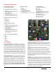
is valid under any of the five supported interface modes (see reverse for
External Connections Detail illustration). When a valid signal is first detected,
the actuator will self-configure to the corresponding interface mode, and all
other interface modes and input leads are disabled until the actuator is next
powered on. The sensitivity or accuracy of the actuator control algorithm can
be set by adjusting the “Accuracy” trim potentiometer. Turning clockwise wil
l
allow the actuator to move in smaller increments and be more accurate.
However, due to the differences in actuator types this may cause jittery or
unstable behaviour. If this occurs, consider using the USB configuration
program to more finely tune the controller for your application. Each time a
control potentiometer is adjusted, power must be cycled to the LAC board
prior to the new settings taking effect. Adjusting the “Speed” potentiometer
will set the maximum actuator speed. The two “Limits” potentiometers allo
w
user settable digital limit switches. These set the minimum and maximum
acceptable positions. Control inputs that exceed these limits will cause the
actuator to position to the limit.
Copyright 2016
Actuonix Motion Devices
Specifications
Control input modes
Digital: USB, RC Servo, 1 kHz PWM
Analog: 0–3.3 V, 4–20 mA
Controller 10-bit Dual Sample Rate Quasi PD
Compatible actuators
P
Q
12
& L12
-
P
A
ct
u
a
to
rs
wit
h
po
s
iti
o
n
f
ee
db
ack,
6
o
r
12
v
olt
s
L16, P16 & T16 -P Actuators with position feedback, 6 or 12 volts
Larger Actuators with position feedback, 12 volts, 24 volts
Dimensions 50 mm x 50 mm (excluding battery holder)
Power 5–24 VDC, 4 Amps peak current at 10% duty cycle
Operating environment –10 to +70°C at 10–80% relative humidity